Wireless computer system with latency masking

Active Publication Date: 2007-12-25
ADVANCED MICRO DEVICES INC
View PDF40 Cites 45 Cited by
  • Summary
  • Abstract
  • Description
  • Claims
  • Application Information

AI Technical Summary

Problems solved by technology

One problem with system 10 and particularly with WLAN module 17 is system partitioning.
For some wireless transmission sequences, the PCI bus latencies may be greater than the time that system 11 requires to store the data into wireless module 17, thus, the system can not provide the data in sufficien

Method used


Image

  • Wireless computer system with latency masking
  • Wireless computer system with latency masking
  • Wireless computer system with latency masking

Examples


Example

DETAILED DESCRIPTION OF THE DRAWINGS

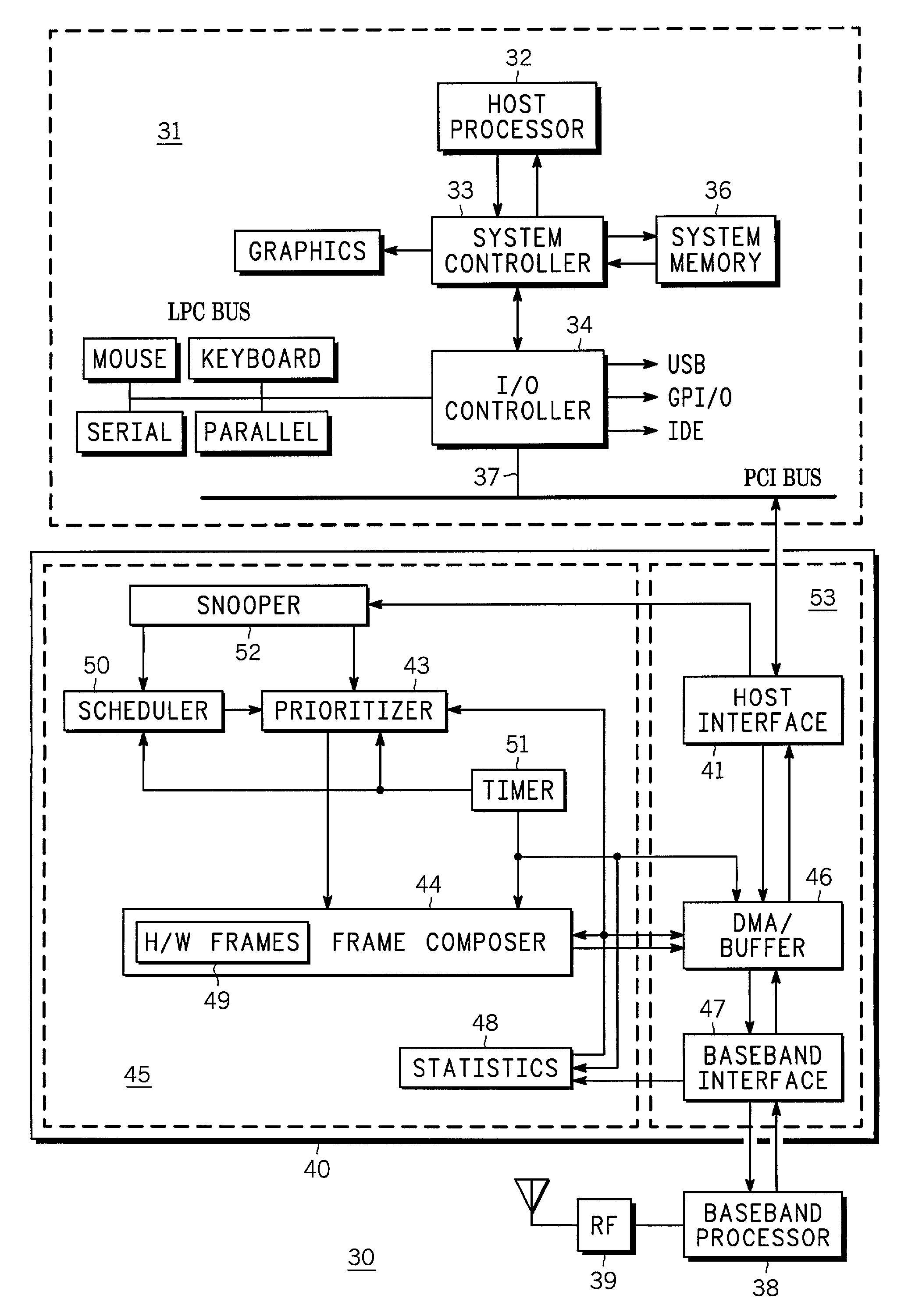
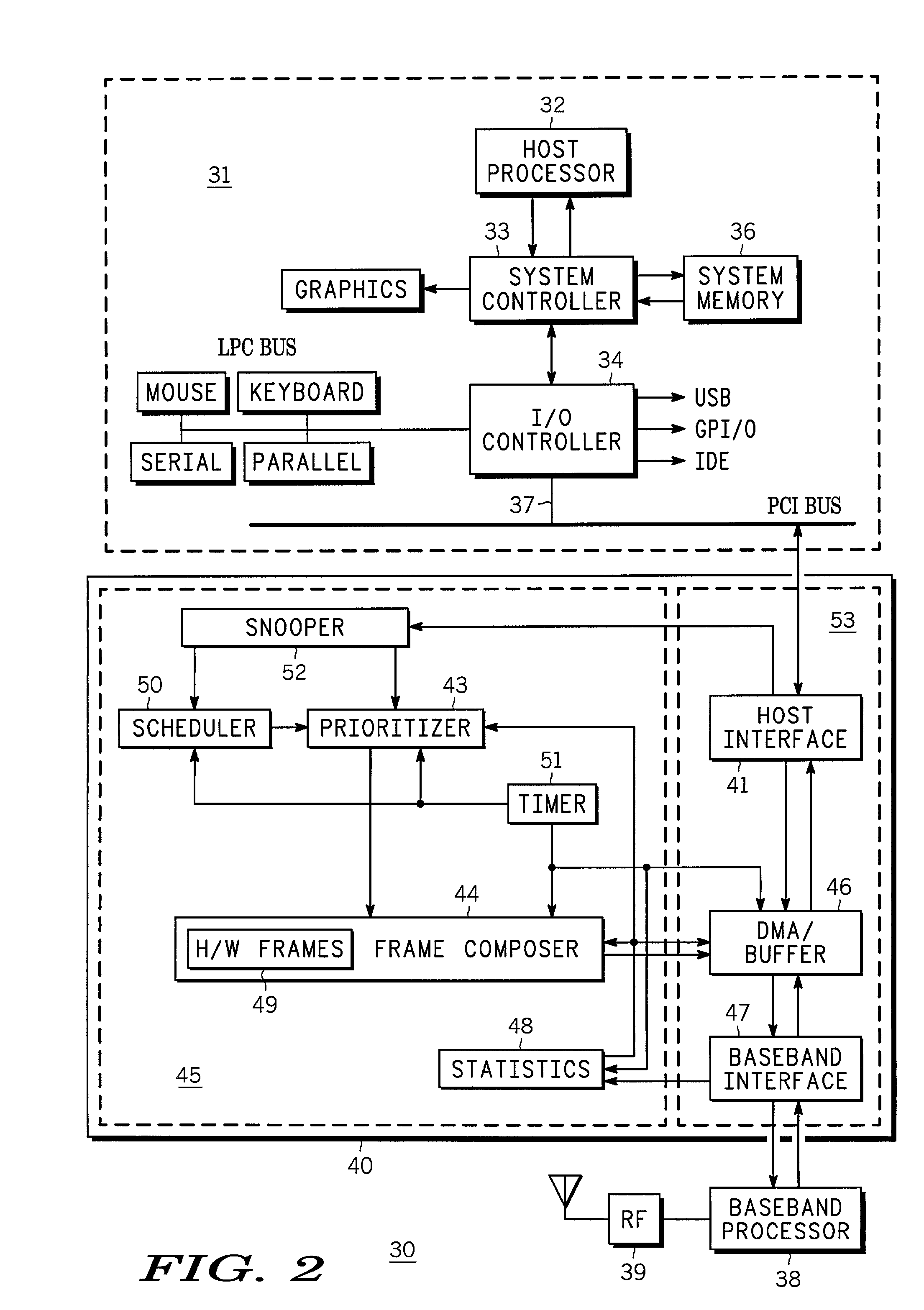
[0019]FIG. 2 is a system block diagram schematically illustrating functional portions of an embodiment of a wireless computer system 30. As will be seen in the descriptions hereinafter, wireless computer system 30 minimizes the cost of forming a wireless computer system and also improves both the throughput and the system partitioning by utilizing portions of system memory for storing information that is to be transmitted over a wireless channel or wireless network by wireless computer system 30. In order to have the information from system memory available for transmission as required by the protocol, wireless computer system 30 partitions the tasks that are to be performed into different types of tasks and forms frame queues for each type of task, the various task differentiated frame queues are formed in different system areas based on the task. As will be seen hereinafter, the information downloaded has a variable length depending on the task ...


PUM


Abstract

A wireless computer system (30) is formed to have a host section (31) and a wireless hardware section (40). A first portion of a transmission frame is formed in system memory (36) of a host section (31) and a second portion of the transmission frame is formed in the wireless hardware section (40). The wireless hardware section (40) begins transmitting the first transmission frame portion while downloading the second transmission frame portion from the system memory (36) into the wireless hardware section (40). Bus latencies are masked by at least overlapping transmitting the first portion of the transmit frame while downloading the second portion.

Description

BACKGROUND OF THE INVENTION[0001]This application claims priority to previously filed English language provisional application No. 60 / 343,737 filed on Dec. 28, 2001 entitled Wireless Computer System With Queue And Scheduler, having at least one common inventor.[0002]The present invention relates, in general, to computer systems, and more particularly, to wireless computer systems.[0003]A wireless computer system usually is a computer system that has the capability to utilize wireless communication techniques to provide interconnectivity between a computer and elements within a network such as interconnectivity to another computer, servers, and even wired networks. One example of a wireless computer network is commonly referred to as a wireless local area network (WLAN). WLANs and other wireless computer networks provide computer users mobility and remove the constraint of having a network cable physically attached to a computer. WLANs typically are used to augment wired networks, fo...

Claims


Application Information

Patent Timeline
IPC IPC(8): H04B7/00H04J3/24H04L12/28H04L12/56
CPCH04W99/00H04W84/12
Inventor KERN, WILLIAM F.ROSNER, STEPHANFLEMMING, RALFNOVAK, STEPHEN T.
Owner ADVANCED MICRO DEVICES INC
Why Eureka
Try Eureka