
High efficient hydrogen generation with green engergy powers

Inactive Publication Date: 2011-06-30
LI HAIMING
View PDF12 Cites 34 Cited by
  • Summary
  • Abstract
  • Description
  • Claims
  • Application Information

AI Technical Summary

Benefits of technology

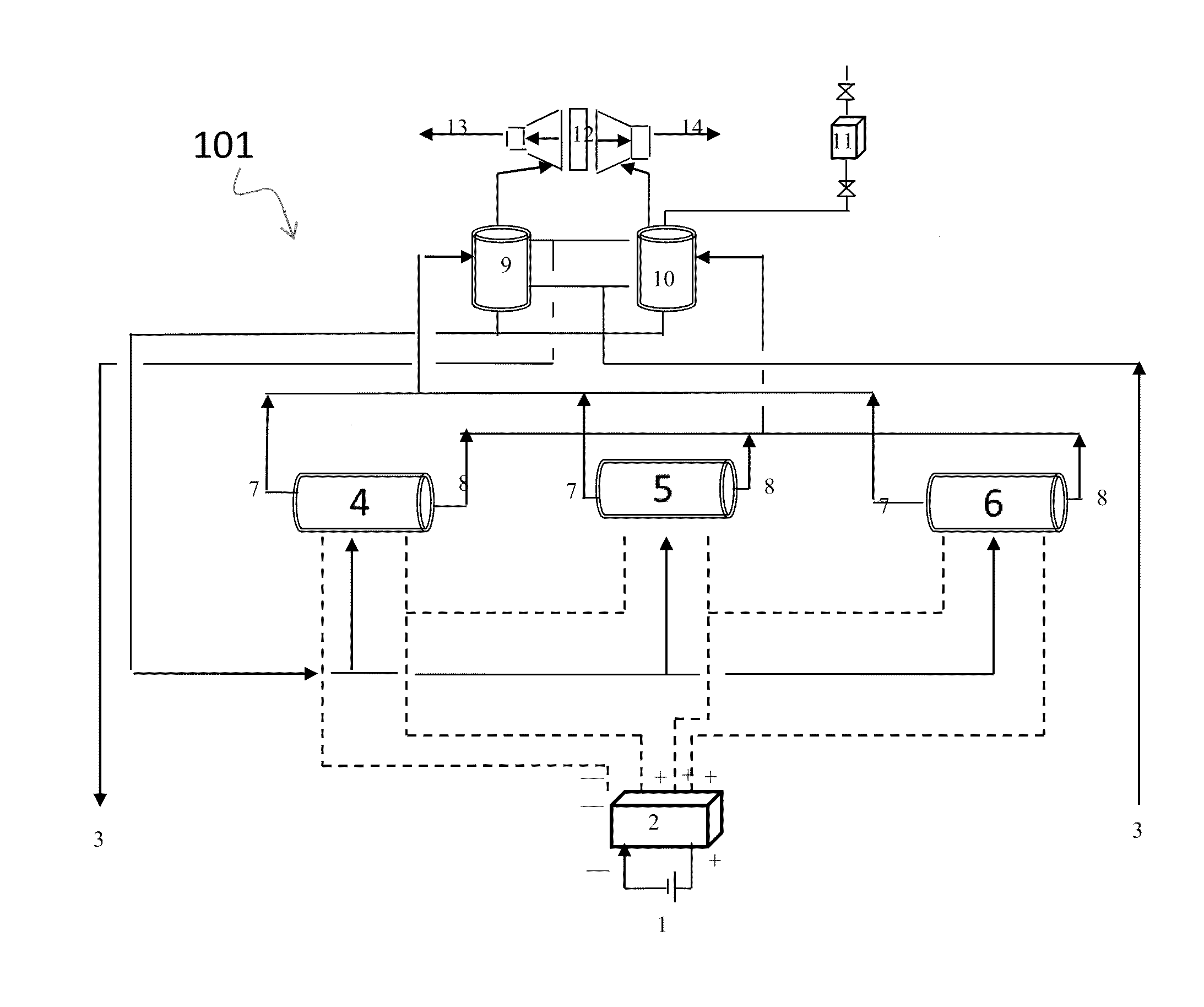
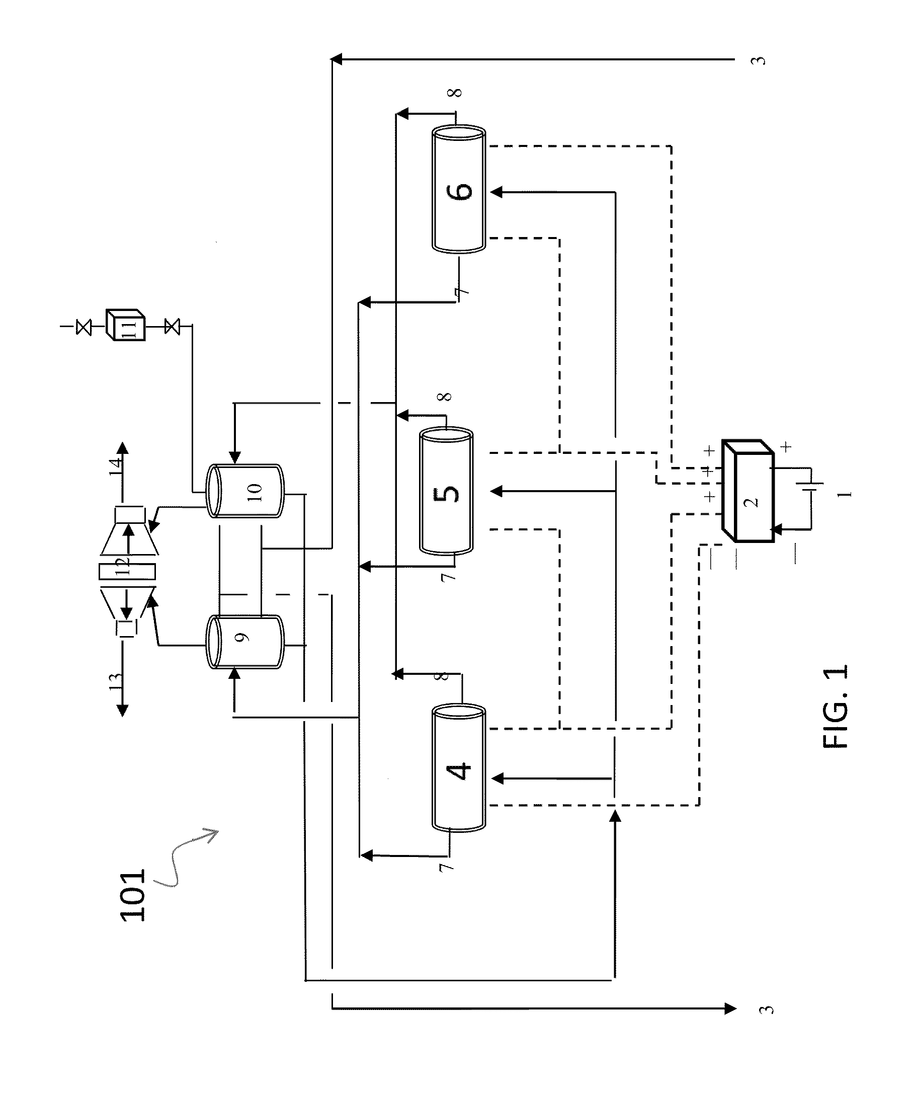
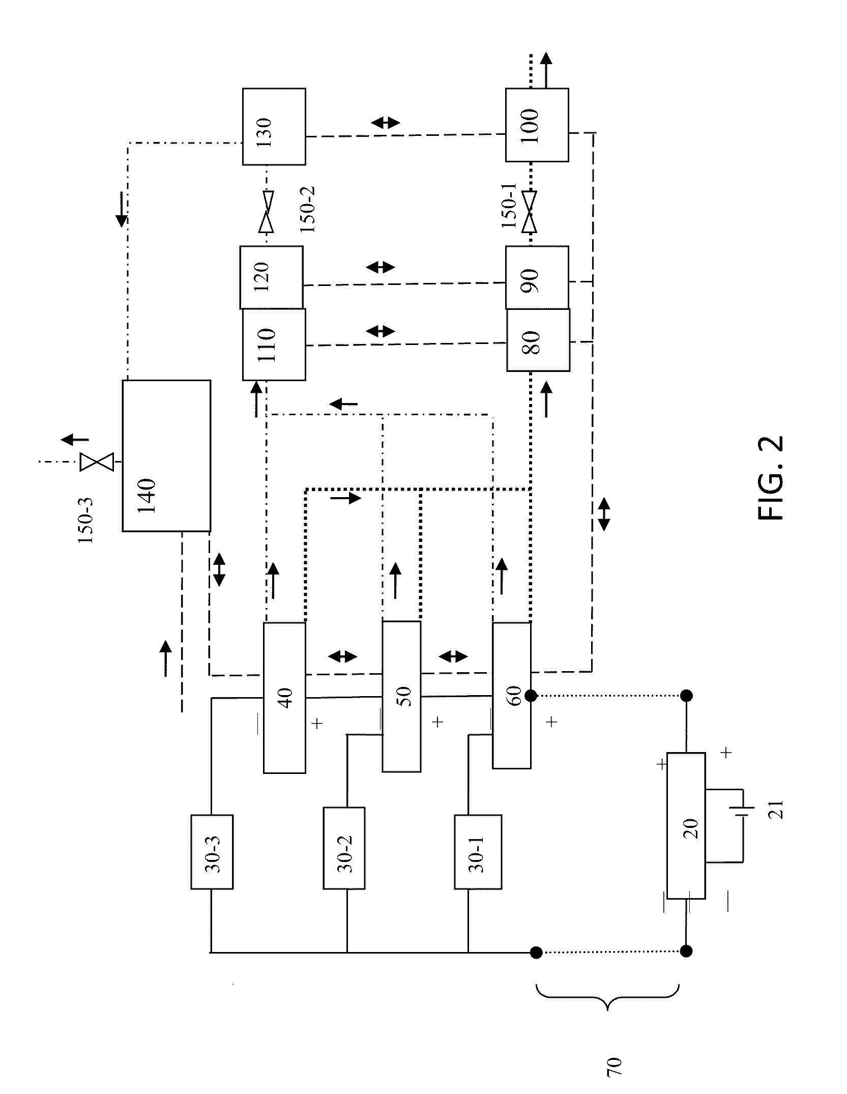
[0012]In one embodiment, the microchip controlling system takes input parameters from an input interface which presets the maximum range of system working voltages / currents and the maximum number of electrolysis stacks / cells, to prevent the system from being over charged.
[0017]The disclosed innovation, in various embodiments, provides one or more of at least the following advantages. However, not all of these advantages result from every one of the innovations disclosed, and this list of advantages does not limit the various claimed inventions. This system and method provide great flexibility and capability in adding and reducing the number of electrolysis units, allowing this hydrogen generation system be operated in high efficiency with variety of green energy power sources that produce a non-stable and intermittent electricity in wide amplitude of fluctuations. The combination of high flexibility and high efficiency will greatly reduce the cost of hydrogen and improve the popularity of hydrogen in replacing fossil fuels as a fuel energy source.

Problems solved by technology

However, traditionally wind and solar energies used in hydrogen electrolysis have inherent disadvantages that prevent them from being effectively and fully utilized.
Because their powers are intermittent and non-dispatchable, for example, when winds are strong, the output would be higher than power demands of a traditional electrolysis system, a great portion of generated energy would be wasted.
Because of this low conversion efficiency, producing hydrogen from water is of high cost, preventing hydrogen from being used as a fuel source of any significance.
However, this design dramatically increases the complexity in safety control of the electrolysis process, and also requires additional energy in generating sufficient heat for high temperature electrolysis.
Such combination, although may improve the efficiency, is limited by their inherent limitations in responding to wider range of fluctuations.
For large singular solar panel system, and for wind powered system, however, because of the number of choices of panels in turning on or off being limited, this method will not be applicable.
On the other hand, for a system that includes hundreds or thousands of small photovoltaic cells, the controlling system will become tremendously complicated, and thus become error prone and useless.

Method used


Image

  • High efficient hydrogen generation with green engergy powers
  • High efficient hydrogen generation with green engergy powers
  • High efficient hydrogen generation with green engergy powers

Examples


Embodiment Construction

[0026]The numerous innovative teachings of the present application will be described with particular reference to presently preferred embodiments (by way of example, and not of limitation). The present application describes several embodiments, and none of the statements below should be taken as limiting the claims generally.

[0027]For simplicity and clarity of illustration, the drawing figures illustrate the general manner of construction, and description and details of well-known features and techniques may be omitted to avoid unnecessarily obscuring the invention. Additionally, elements in the drawing figures are not necessarily drawn to scale, some areas or elements may be expanded to help improve understanding of embodiments of the invention.

[0028]The terms “first,”“second,”“third,”“fourth,” and the like in the description and the claims, if any, may be used for distinguishing between similar elements and not necessarily for describing a particular sequential or chronological or...


PUM


Abstract

A novel system and method for generating hydrogen by electrolysis of water from a green power source. Electricity generated by solar panel or wind mill is measured and connected with plurality of electrolysis stacks. The number of operating electrolysis stacks are constantly controlled by a controlling mechanism that calculates an optimal operating number of electrolysis stacks using the measured electricity parameter and the operating parameter of an electrolysis unit.

Description

CROSS-REFERENCE[0001]Priority is claimed from the U.S. Provisional Application No. 61 / 313,711, filed on Mar. 13, 2010, and the entirety of which is hereby incorporated by reference.DESCRIPTION OF RELATED ART[0002]The present application relates to a hydrogen generation system, and more particularly to a high efficient hydrogen generation system that adjusts to fluctuations and variations of the input power source, thus efficiently converting a green energy source into hydrogen fuel energy.[0003]Note that the points discussed below may reflect the hindsight gained from the disclosed inventions, and are not necessarily admitted to be prior art.[0004]Hydrogen has long been regarded as a clean fuel source alternative to fossil fuel energy sources. Hydrogen is non-polluting, transportable, storable, more efficient than petrol, and can be convertible directly to heat and electricity for both mobile and other applications.[0005]Hydrogen can be generated by a number of ways, the cleanest wa...

Claims


Application Information

Patent Timeline
IPC IPC(8): C25B1/04C25B9/00
CPCC25B1/04C25B15/02Y02E70/10Y02E60/366C25B15/08Y02E60/36
Inventor LI, HAIMING
Owner LI HAIMING
Learn More