Method and apparatus for intra-articular injection or aspiration

a technology of intraarticular injection and aspiration, which is applied in the field of fluid exchange within the joint, can solve the problems of pain and swelling in the patient's joint, difficulty in correctly locating and difficulty in correct positioning the needle tip in the synovial cavity

Inactive Publication Date: 2010-10-28
TING CHOON MENG
View PDF23 Cites 37 Cited by
  • Summary
  • Abstract
  • Description
  • Claims
  • Application Information

AI Technical Summary

Benefits of technology

[0094]inserting the needle slowly into the knee and causing a fluid to pass continuously through the needle and into the patient;

Problems solved by technology

A barrier to acceptance of this procedure by health care professionals is the perceived difficulty in correctly locating the needle in the synovial cavity.
A barrier to acceptance of the procedure by health care professionals is the perceived difficulty in correctly locating the needle tip in the synovial cavity.
In the instance the synovial cavity is not correctly located and hyaluronic acid is injected into any other location of the joint a severe hyper immune response will result in the patient's joint, including pain and swelling.
Similar problems exist in relation to the injection of fluid into or the aspiration of fluids from a joint.

Method used


Image

  • Method and apparatus for intra-articular injection or aspiration
  • Method and apparatus for intra-articular injection or aspiration
  • Method and apparatus for intra-articular injection or aspiration

Examples


first embodiment

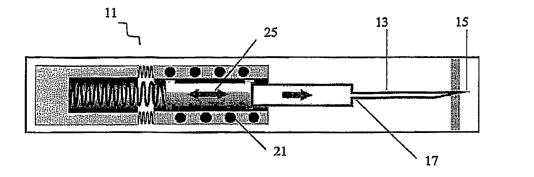
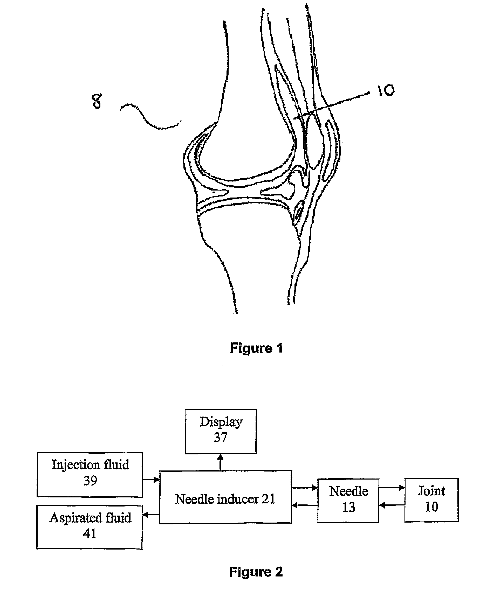
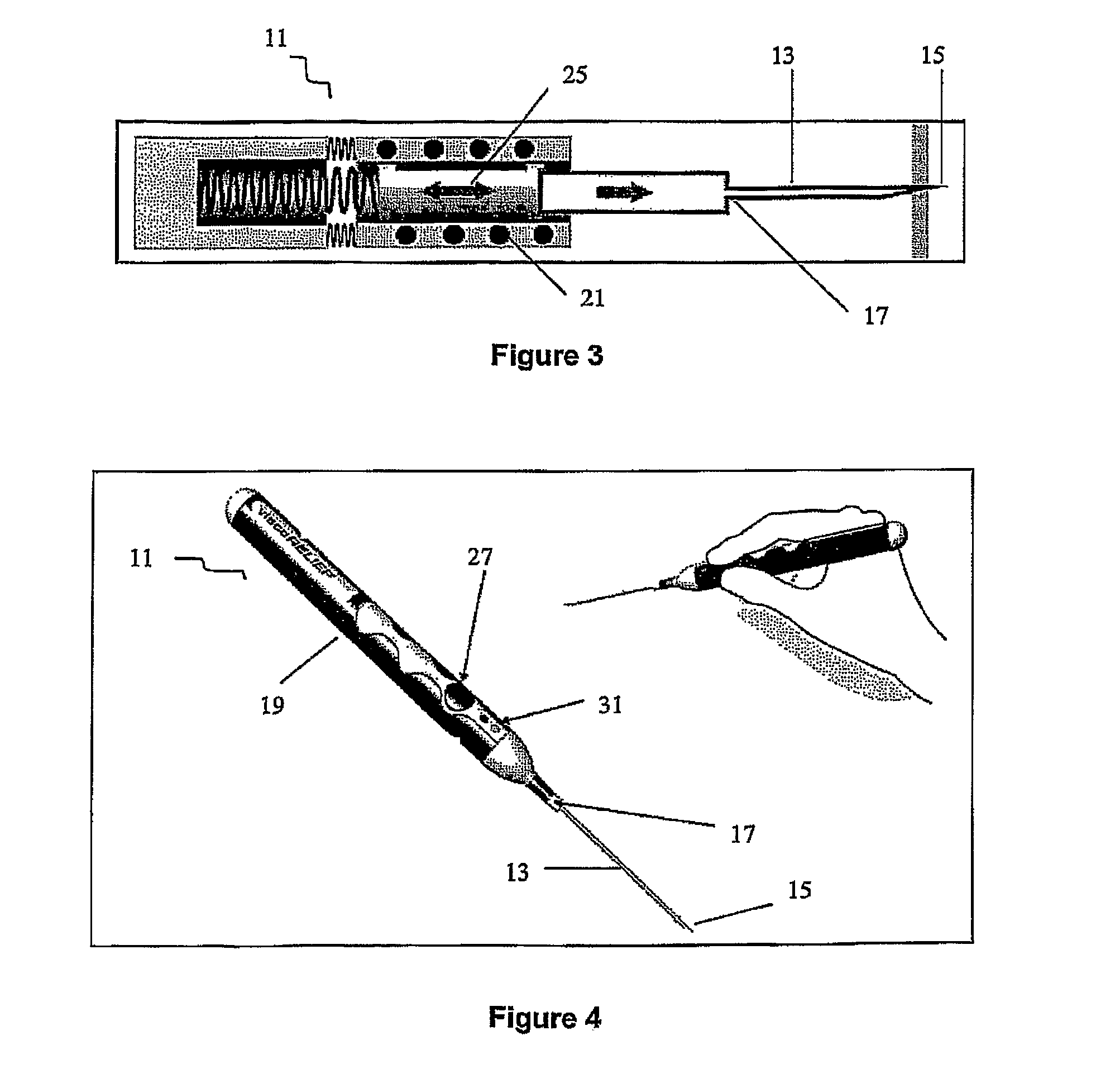
[0125]FIG. 1 is a schematic of the anatomy of a knee joint 8. Referring to FIGS. 1 and 2, the invention is in the form of a medical apparatus 11 for performing Visco supplementation. FIG. 2 is a block diagram of a medical apparatus 11 according to an embodiment of the invention. The apparatus 11 comprises a hollow piercing member, in the form of a needle or cannula 13 through which a fluid may pass. The needle / cannula 13 has a first end 15 adapted to pierce the skin of a patient, and a second end 17 releasably secured to a body 19. The body 19 incorporates an inducer 21 to induce pulses within the apparatus 11

[0126]The apparatus 11 also comprises a sensing means 23 wherein upon entering a cavity of the patient the sensing means 23 senses pulse differentials which result when the first end 15 of the needle / cannula 13 enters the cavity. Such as the synovial joint cavity 10 shown in FIG. 1.

[0127]A first embodiment of the invention is shown in FIGS. 3, 4, and 5a. In this embodiment the...

second embodiment

[0128] the force pulse is generated by eccentrically mounting a fly wheel 29 within the body 19, as shown in FIG. 5b.

[0129]In both the first and second embodiments the force pulse is generated by the inertia effects of the mass 25 and flywheel 29 respectively. When the first end 15 of the needle / cannula 13 enters a region of different viscosity such as the cavity, the change in inertial kickback is experienced. This change provides a physical indication to the operator that the first end 15 is in the cavity. The sensing means 23 in the form of an accelerometer 24 also senses the change and a visual indicator 31 on the body 19 indicates to the operator that the cavity has been entered.

third embodiment

[0130]Referring to FIGS. 7 to 12, the invention is shown. In this embodiment the pulses are in the form of pressure pulses which are induced in the fluid travelling through a tube 33 which is in fluid communication with the needle / cannula 13. The pressure pulses form at a known frequency and pressure.

[0131]The sensing means 23 in this embodiment is in the form of a transducer 35 which measures the change in resistance at the first end 15 of the needle / cannula 13.

[0132]Referring to FIGS. 9 and 10, the apparatus 11 is connected to a display unit 37, which incorporates a pump unit 38, a saline bag 39 and an effusion bag 41. The display of the display unit 37 may take many forms, an example of which is shown in FIG. 11. On this display is an indicator lamp 43 which is highlighted when first end 15 enters the cavity.

[0133]The pump unit 38 comprises two peristaltic pumps 45, each designated to either move fluid out the saline bag 39 or into the effusion bag 41 to ensure there is no cross ...


PUM


Abstract

A medical apparatus for an intra-articular injection or aspiration, the apparatus having a hollow piercing member through which fluid may pass, the piercing member having a first end adapted to pierce a patient, and a second end releasably secured to a body; a sensing means, wherein upon entering a cavity of the patient the sensor means senses the change in resistance at the first end of the piercing member which results when the first end of the piercing member enters the cavity.

Description

CROSS-REFERENCE TO RELATED APPLICATIONS[0001]This application is a U.S. National Stage application of International Application Serial No. PCT / SG2009 / 000010 filed Jan. 6, 2009.FIELD OF THE INVENTION[0002]The present invention generally relates to fluid exchange within a joint. In particular the invention relates to a method and apparatus for intra-articular injection or aspiration.BACKGROUND ART[0003]Osteoarthritis (arthritis) joints result when the synovial fluid has lost elasticity and viscosity, resulting in a reduction in the lubricating and shock absorbing properties of the synovial fluid. Visco supplementation is a procedure that involves the injection of gel-like substances (hyaluronates) into a joint to supplement the elastic and viscous properties of the synovial fluid. Visco supplementation restores the shock-absorbing and lubricating properties of the synovial fluid in, for example, an arthritic knee joint.[0004]The current procedure requires a health care professional to...

Claims


Application Information

Patent Timeline
Patent Type & Authority Applications(United States)
IPC IPC(8): A61M5/42
CPCA61B17/3403A61M5/20A61M5/14232A61B2019/464A61B2090/064
Inventor TING, CHOON MENG
Owner TING CHOON MENG
Why Eureka
Try Eureka