Self-anchoring coronary sinus lead

a coronary sinus lead and self-anchoring technology, which is applied in the direction of internal electrodes, transvascular endocardial electrodes, therapy, etc., can solve the problems of affecting the patient's life, affecting the patient's comfort, so as to achieve the effect of easily traversing the bend

Inactive Publication Date: 2007-12-25
PACESETTER INC
View PDF7 Cites 95 Cited by
  • Summary
  • Abstract
  • Description
  • Claims
  • Application Information

AI Technical Summary

Benefits of technology

[0010]Another aspect of the invention relates to electrode configuration. Two electrodes provide for bipolar pacing and sensing. The benefits of the bipolar configuration are well known. In addition to the tip electrode at the distal end of the lead, at least one ring electrode may be place anywhere proximal to the distal tip electrode. That is, a ring electrode may be placed on, before, or after the curve of either one of the two bends. In the preferred embodiment, the ring electrode is placed on the straight portions, either before or after the bends so that a stylet can more easily traverse the bends. Thus, the electrodes may be located in the same geometric plane and oriented approximately 180 degrees apart. The coronary veins are located on the surface of the epicardium. The inside wall of the vein is adjacent to the myocardium and the outside wall of the vein is adjacent to the pericardium. Only the myocardium is excitable. Consequently, placement of electrodes may be forgiving if one electrode is oriented toward the pericardium and the other electrode is oriented toward the myocardium. Thus, at least one electrode may be capable of performing low threshold stimulation.
[0011]Another feature of the design allows for placement of the lead over a guidewire. A guidewire may be placed in the coronary sinus using a catheter, such as the 7F CSL catheter manufactured by DAIG. Once the CSL catheter is in position, a guidewire may be advanced through the catheter. The guidewire may be selectively positioned into the coronary sinus.

Problems solved by technology

However accessing the left chambers of the heart is more difficult than accessing the right chambers of the heart.
Dislodgment of any portion of the lead located in the left atrium and / or ventricle may result in immediate patient death.
Several difficulties are associated with placing a lead transvenously to stimulate the left chambers of the heart.
Lead placement into the coronary sinus region is often hindered and, sometimes, obstructed by narrow pathways and curvatures.
This kind of lead may be vulnerable to several problems when placed into the coronary sinus.
In view of its helical structure, this lead may be more difficult to manufacture than ordinary leads.
Moreover, the helical end of the lead may not maintain intimate or continuous contact with the inner wall of the vessel.
The inability to maintain intimate contact may result from the difficulty of maintaining a geometrically uniform helical structure in the lead.
The inability to maintain contact may also be due to inherent anatomical variations of coronary vessels.
Moreover, the lack of continuous contact with vessel wall makes it difficult to ensure proper contact of electrodes placed in the helical structure with the inner wall of the vessel.
Lacking contact by the electrodes with the inner wall of the vessel renders cardiac stimulation ineffective or sensing inaccurate.
Hence, as noted above, adequate fixation of the lead and electrode in a coronary vessel is difficult to achieve.
A small electrode, less than the diameter of the vessel, is likely to move easily within the vessel and may not be adequately affixed which results in displacement or dislodgment of the lead.

Method used


Image

  • Self-anchoring coronary sinus lead
  • Self-anchoring coronary sinus lead
  • Self-anchoring coronary sinus lead

Examples


Embodiment Construction

[0034]The following description is not to be taken in a limiting sense, but is made merely for the purpose of describing the general principles of the invention. The scope of the invention should be determined with reference to the claims.

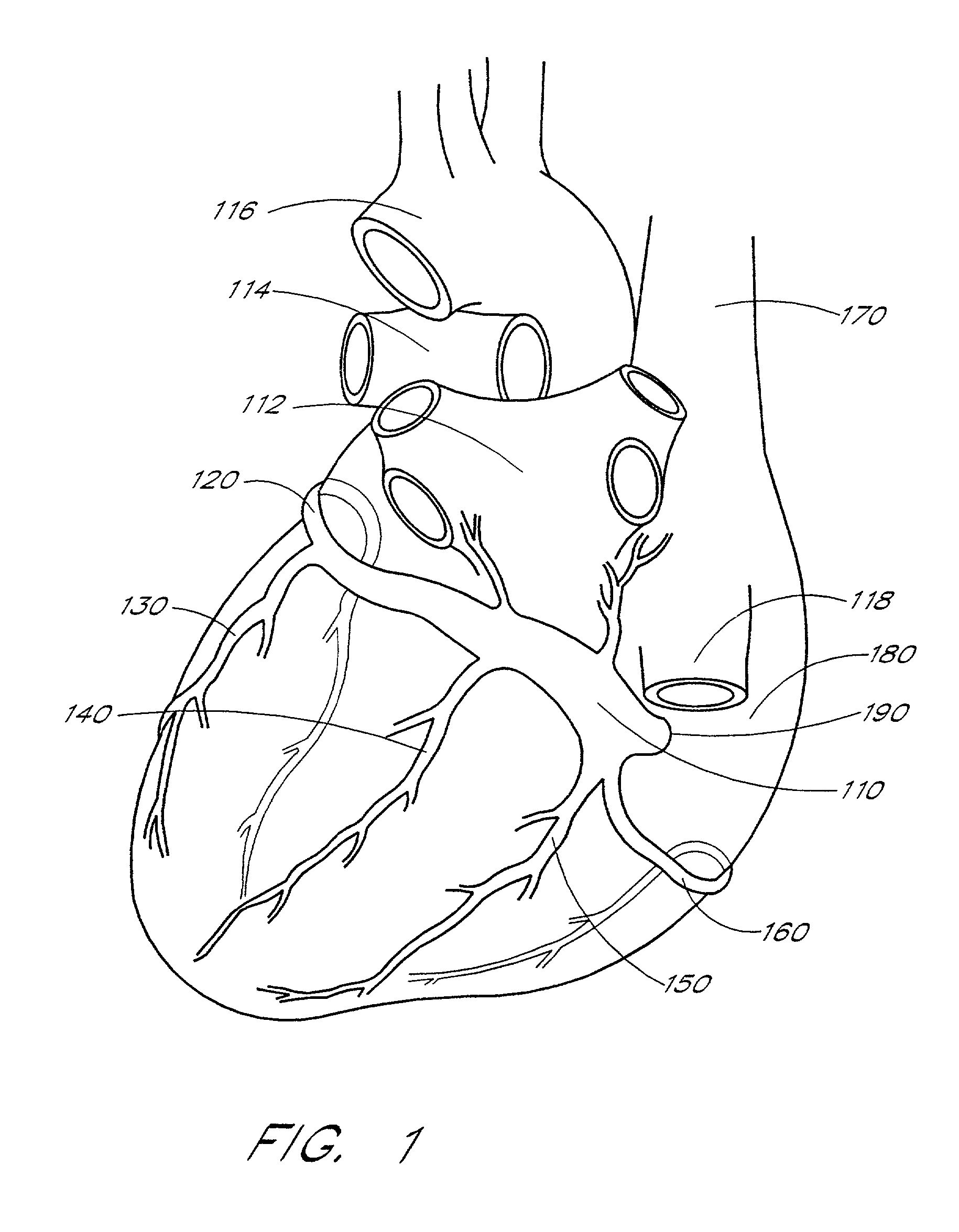
[0035]As indicated above, the invention provides an implantable lead system for placement in difficult-to-reach regions of the heart. To better understand the details of the invention, an overview of the relevant anatomy of the coronary sinus region of the heart is first provided. FIG. 1 is a perspective view of the left-posterior region of the heart 100. As shown in FIG. 1, the coronary sinus vein 110 is the main vein of the heart. Typically, the coronary sinus vein 110 is a venous channel of about 2 centimeters in length which runs from right to left in the posterior part of the coronary groove. The coronary sinus vein 110 connects to the great cardiac vein 120 at its left end. Moreover, the coronary sinus vein 110 connects to the left marginal v...


PUM


Abstract

An implantable cardiac lead system suitable for placement in the coronary sinus region of the heart. The lead system comprises a lead having two or more non-helical bends in its distal portion. The two or more non-helical bends cooperate to prevent the lead from dislodgment or displacement inside the coronary sinus. The lead system may further comprise a stylet suitable for steering the lead into at least one of the coronary sinus vein, great cardiac vein, left marginal vein, left posterior ventricular vein, and small cardiac vein. The stylet is tapered in its distal portion to provide enhanced maneuverability and steerability inside the coronary sinus region. The lead system may also comprise an introducer which aids in introducing the lead into the heart.

Description

CROSS-REFERENCE TO RELATED APPLICATIONS[0001]This application is a continuation of U.S. patent application Ser. No. 09 / 457,277, filed Dec. 8, 1999, now abandoned which is a continuation-in-part of U.S. patent application Ser. No. 09 / 196,898, filed Nov. 20, 1998 now abandoned.FIELD OF THE INVENTION[0002]The invention relates to implantable stimulation leads. More particularly, the invention relates to an intravenous cardiac lead placed in the coronary sinus and into the vein(s) of the heart to provide pacing of the left atrium and / or left ventricle.BACKGROUND OF THE INVENTION[0003]To perform cardiac pacing, a lead system is typically positioned in the right chambers of the heart (i.e. right atrium and / or ventricle) through the superior vena cava (SVC). Sometimes, it is desirable to perform sensing, pacing, and / or defibrillation of the left atrium and / or ventricle. However accessing the left chambers of the heart is more difficult than accessing the right chambers of the heart. The le...

Claims


Application Information

Patent Timeline
Patent Type & Authority Patents(United States)
IPC IPC(8): A61N1/05
CPCA61N1/056A61N1/057A61N2001/0585A61N2001/0578
Inventor PIANCA, ANNE M.MORGAN, KEVIN L.BORNZIN, GENE A.FLORIO, JOSEPH J.VACHON, DAVID J.
Owner PACESETTER INC
Why Eureka
Try Eureka