Insert for cooler

a technology for inserts and coolers, applied in the direction of cooling fluid circulation, defrosting, lighting and heating apparatus, etc., can solve the problems of unfavorable changes in the texture or flavor of foodstuffs, corners tend to accumulate dirt, draining apertures, etc., and achieve the effect of facilitating the cleaning of inserts

Inactive Publication Date: 2008-01-01
GIRARD LUCIEN
View PDF10 Cites 22 Cited by
  • Summary
  • Abstract
  • Description
  • Claims
  • Application Information

AI Technical Summary

Benefits of technology

[0009]Another advantage of the present invention is that the size of the insert can be adapted for fitting the insert to a variety of sizes of cooler.
[0010]According to a first aspect of the present inventIon, there is provided an Insert for placement on a lower surface of an interior portion of a cooler for maintaining foodstuffs therein in a cool state, the lower surface being bounded by at least one cooler wall extending therefrom. The insert comprises:
[0011]a first surface having at least one leg extending vertically therefrom for supporting the insert upon the lower surface and defining a space therebetween;
[0012]a second surface, generally opposed to the first surface and upon which the foodstuffs rest when placed in the cooler; and
[0013]at least one elongated curved draining aperture extending through said insert for drainage of liquid in the cooler away from the foodstuffs and into said space, each said draIning aperture being defined by at least one elongate internal wall having at least one curved section, said draining aperture being sized and adapted for cleaning of said wall by insertion therein of a human finger and scrubbing said wail therewith, said curved section facilitating said scrubbing and thereby said cleaning; and
[0014]at least one guide line disposed on at least one of the first and second surface, the guide line approximately representig a surface size and a surface shape of the lower surface for facilitating cutting of the insert by a user to substantially approximately the surface size and the surface shape for adapting the insert for placement upon the lower surface.

Problems solved by technology

This draining of liquid into the space below the insert separates the liquid from the foodstuffs and impedes substantial impregnation of the foodstuffs by the liquid which may cause, among other things, undesirable changes in texture or flavor of the foodstuffs.
Disadvantageously, however, the draining apertures are, as shown in the drawings, formed in the shape of squares having internal sharp corners.
Such sharp corners tend to accumulate dirt and are difficult to clean manually.
Further, should a user purchase such an insert for a cooler and then replace the cooler with a smaller cooler, the insert may, depending on its size relative to the new, smaller cooler, be unusable therewith.
Unfortunately, the draining apertures, as shown in the drawings, also have sharp internal corners, and thus the insert suffers from the same drawbacks for cleaning as those described above for the insert disclosed in U.S. Pat. No. 5,636,524.
In addition, since the insert taught by U.S. Pat. No. 6,574,983 is hingedly mounted in the cooler, it may not be easily removable, which will further complicate cleaning thereof.
The use of hinges for mounting the insert also signifies that an insert, as taught in the reference, installed in a larger cooler may not be easily adaptable for use in a smaller cooler.
However, when cleaning the insert manually, it may nevertheless be difficult to engage a human finger in a partially bent position therein, possibly with a cleaning instrument on the finger, to clean the interior walls forming the draining apertures.
In addition, the use of circular shapes for the draining apertures requires more draining apertures, and thus more effort for cleaning, than would more elongate shapes.
Further, the side perimeter may provide insufficient support for foodstuffs placed on the center of the insert and may cause the insert to sag or break, possibly exposing the foodstuffs to the liquid in the space thereunder.
An optional support grill disclosed in the reference may circumvent this issue, but the grill is set out in a matrix like format which introduces a large additional amount of surfaces-which must be cleaned, thus making cleaning of the insert, especially manually, more difficult.
Thus, an insert purchased for a larger cooler cannot necessarily be adapted for use in a smaller cooler.

Method used


Image

  • Insert for cooler
  • Insert for cooler
  • Insert for cooler

Examples


Embodiment Construction

[0021]With reference to the annexed drawings the preferred embodiment of the present invention will be herein described for indicative purpose and by no means as of limitation.

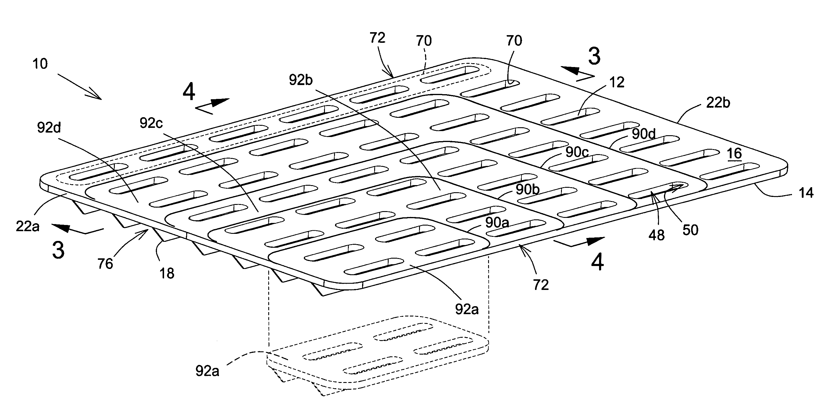
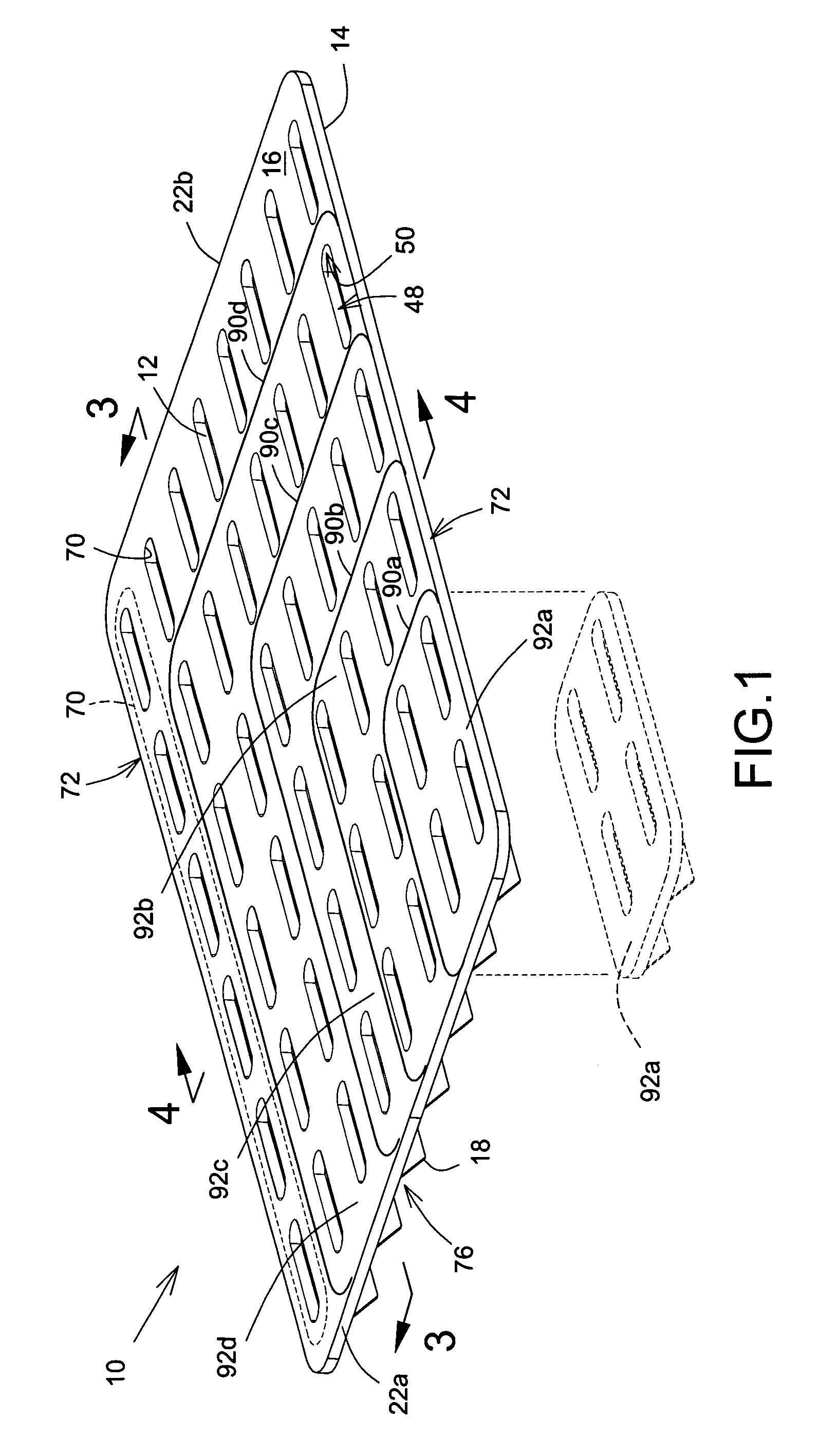
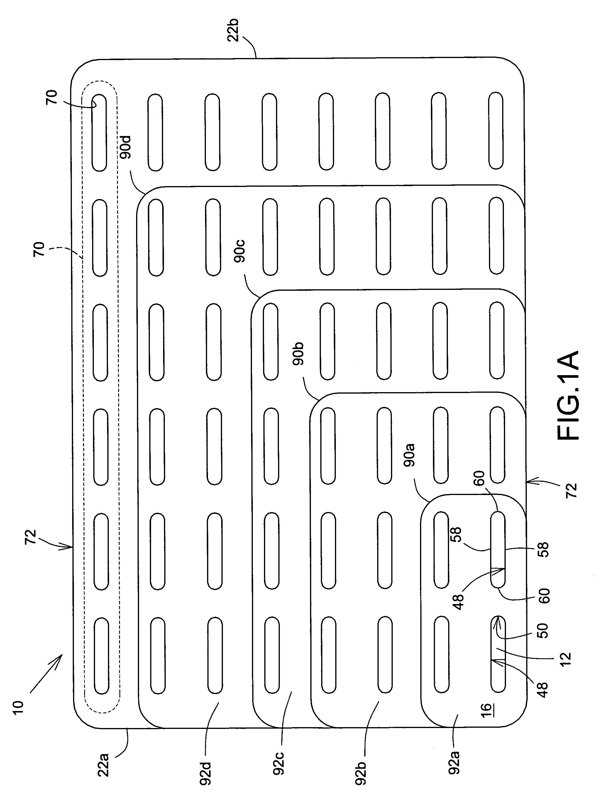
[0022]Referring now to FIGS. 1 and 1A, insert, shown generally as 10, has draining apertures 12 which extend from a first, bottom surface 14 to a second, top surface 16 generally opposed thereto, and through which liquid may pass. Legs 18 for supporting insert 10 extend downwardly from first surface 14 and extend longitudinally between generally opposed first and second insert ends 22 of insert 10.

[0023]Reference is now made to FIG. 2, a perspective view of insert 10 placed in a cooler, shown generally as 30, for cooling and maintaining foodstuffs, not shown, placed therein in a cool state. Insert 10 is placed on lower surface 32 of interior 34 of cooler 30 and rests on lower surface 32 supported by legs 18. Lower surface 32 is bound and defined by cooler walls 36 which extend upwardly therefrom towards an upp...


PUM


Abstract

An insert for a cooler is sized and shaped for placement on a lower surface of the cooler while supporting foodstuffs placed on insert. Draining apertures on insert allow liquid to drain away from foodstuffs into a space below insert and thereby separates liquid from foodstuffs. Draining apertures are formed from internal walls having curved sections and are sized to facilitate insertion of human fingers therein during cleaning, the curved sections and size of apertures facilitating cleaning. Guide lines marked on insert allow insert to be cut to be adapted in size and shape to lower surface of cooler.

Description

FIELD OF THE INVENTION[0001]The present invention relates to inserts for coolers and is more particularly concerned with an insert for placement on a lower surface of the interior of a cooler for foodstuffs.BACKGROUND OF THE INVENTION[0002]It is well known in the art to place inserts into coolers for foodstuffs for providing drainage of liquid away from foodstuffs placed therein. Such inserts, which are often removable, are typically placed with a first, bottom surface thereof situated on or near a lower surface of the interior of the cooler in which the foodstuffs are placed. The foodstuffs usually rest or are placed on a second, top surface of the insert along with a coolant, typically a frozen liquid, such as water frozen into ice. The coolant cools the foodstuffs by absorbing heat therefrom and maintains them in a cool state. However, when the coolant is a frozen liquid, such as water frozen into ice, the coolant is liquefied, i.e. melted into a liquid state, as it absorbs the h...

Claims


Application Information

Patent Timeline
Patent Type & Authority Patents(United States)
IPC IPC(8): F25D3/02
CPCF25D3/08F25D21/14F25D2303/081F25D2400/22
Inventor GIRARD, LUCIEN
Owner GIRARD LUCIEN
Why Eureka
Try Eureka