Leak sensor for flowing electrolyte batteries

a technology of electrolyte batteries and leak sensors, which is applied in the direction of indirect fuel cells, primary cell maintenance/service, instruments, etc., can solve the problems of leakage of electrolyte, likewise problematic cooling systems, and the possibility of failure of one of these components, so as to facilitate the detection of leakag

Inactive Publication Date: 2008-01-01
LARGO CLEAN ENERGY CORP
View PDF4 Cites 13 Cited by
  • Summary
  • Abstract
  • Description
  • Claims
  • Application Information

AI Technical Summary

Problems solved by technology

As the circulation of electrolyte includes a multitude of components, fittings and conduits a potential always exists for failure of one of these components.
Such failure will generally result in a leak of electrolyte.
In addition, since many such batteries require cooling systems which likewise comprise a multitude of conduits fittings and components, the cooling systems are likewise problematic.
Failure in such components generally results in a leak of coolant.
Further still, many such batteries, especially in industrial applications, are placed in a substantially sealed container which remains exposed to harsh environments.
As such, damage to the sealed container often results in the collection of precipitation within the container.
Any leak of electrolyte or coolant, as well as any entry of outside moisture can have catastrophic results.
Specifically, not only will it cause the battery to operate in a less than optimal condition, the battery may completely fail.
If a battery fails, then it is incapable of providing power in an emergency.

Method used


Image

  • Leak sensor for flowing electrolyte batteries
  • Leak sensor for flowing electrolyte batteries
  • Leak sensor for flowing electrolyte batteries

Examples


Embodiment Construction

[0022]While this invention is susceptible of embodiment in many different forms, there is shown in the drawings and will be described in detail, one specific embodiment with the understanding that the present disclosure is to be considered as an exemplification of the principles of the invention and is not intended to limit the invention to the embodiment illustrated.

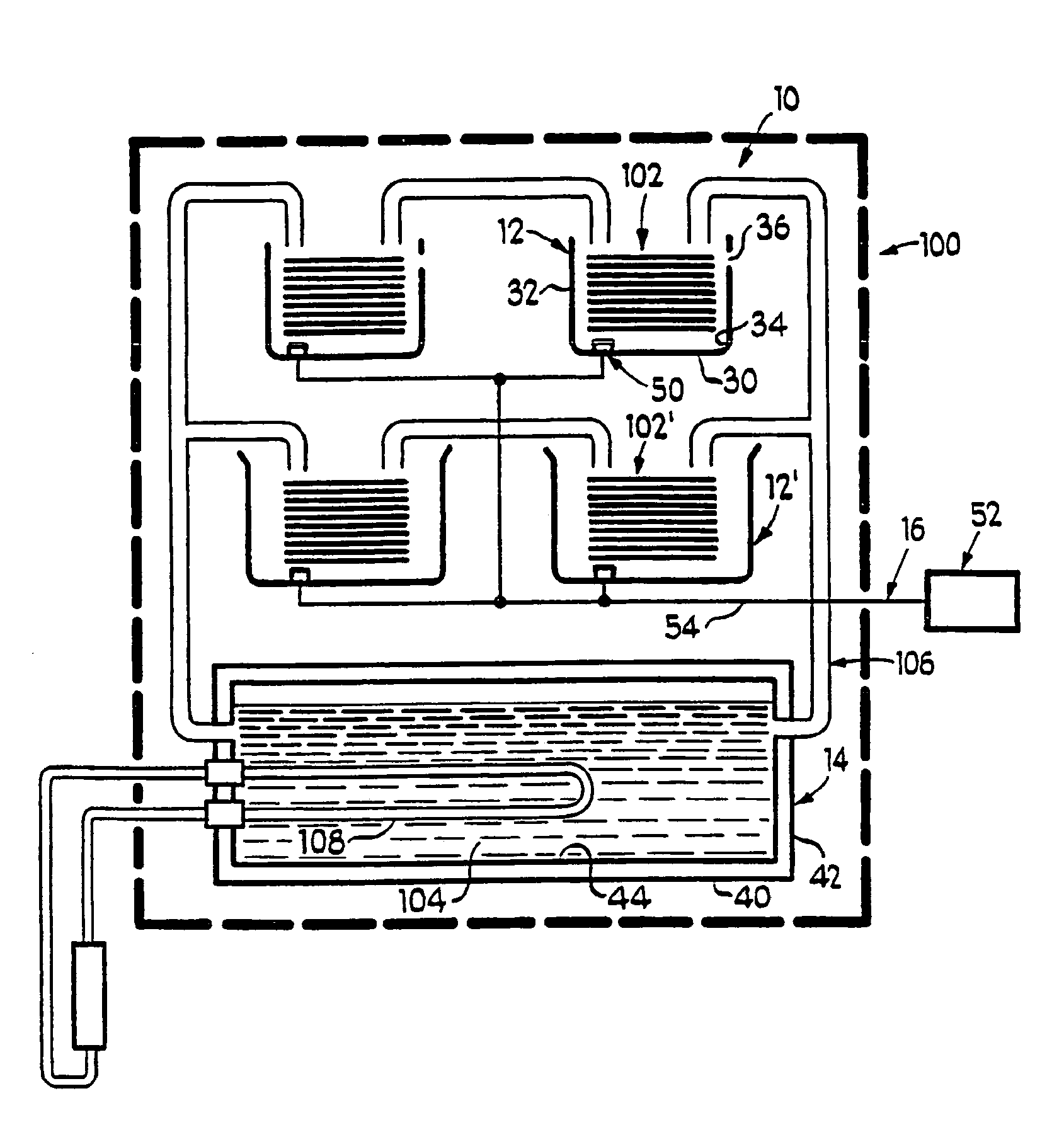
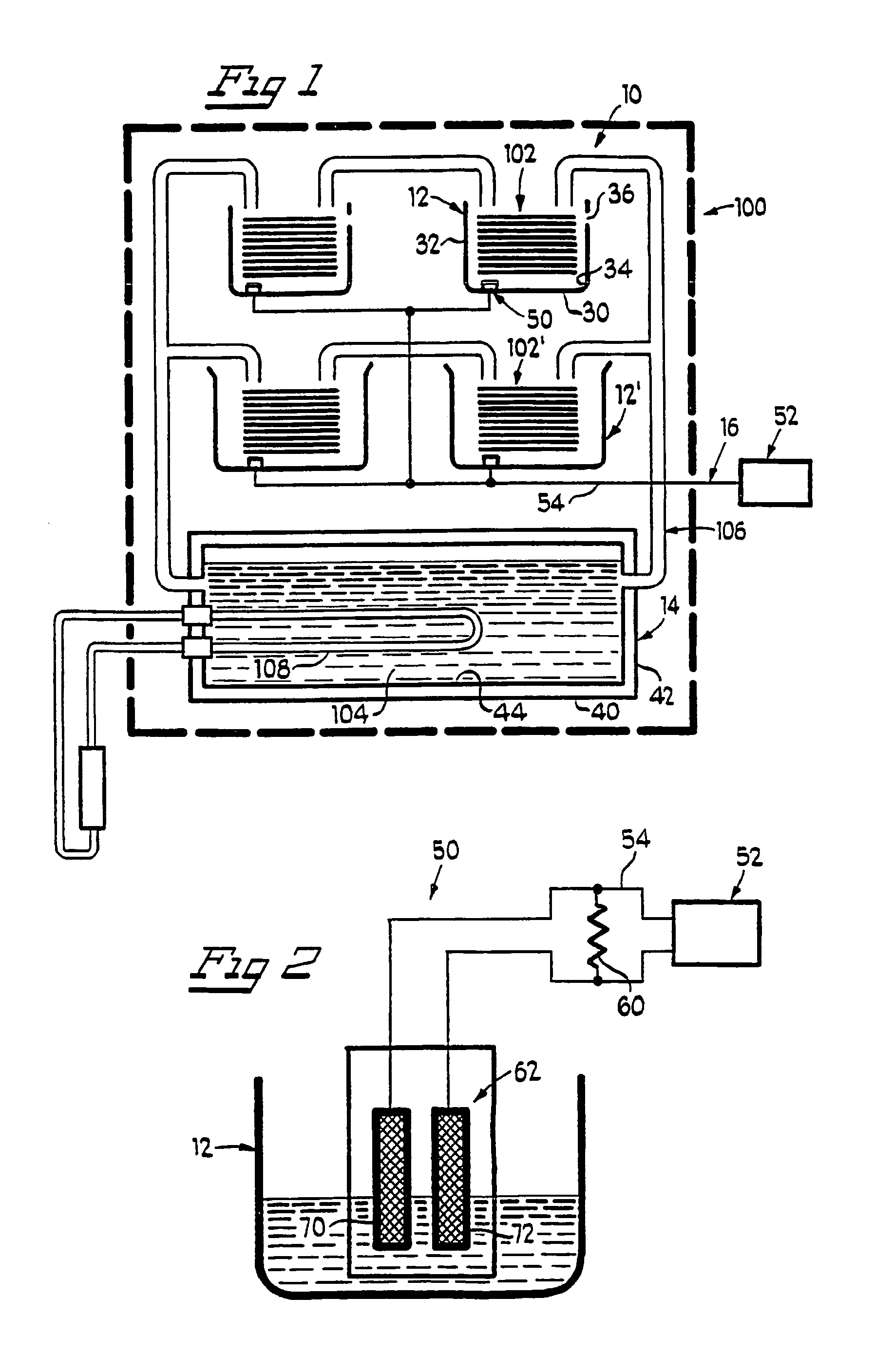
[0023]Leak detection system 10 is shown in FIG. 1 as comprising stack leak containment member 12, reservoir leak containment member 14 and means 16 for sensing a leak. Leak detection system 10 is for use in association with a flowing electrolyte battery, such as zinc / bromine battery 100. While various flowing electrolyte batteries are contemplated for use, the invention will be described with reference to a zinc / bromine battery solely as an example. Generally, zinc / bromine battery 100 includes one or more stacks, such as stack 102, electrolyte reservoir 104, circulating means 106 and means 108 for controlling the climat...


PUM

PropertyMeasurementUnit
voltageaaaaaaaaaa
electric currentaaaaaaaaaa
currentaaaaaaaaaa

Abstract

A leak detection system for a flowing electrolyte battery comprising a containment member associated with at least one of a stack of a flowing electrolyte battery and an electrolyte reservoir of a flowing electrolyte battery and a sensing member for sensing a fluid leak within the containment member.

Description

BACKGROUND OF THE INVENTION[0001]1. Field of the Invention[0002]The invention is directed to flowing electrolyte batteries, and in particular to a leak sensor for use in association with flowing electrolyte batteries such as zinc / bromine batteries. It will be understood that the application is not limited to any zinc / bromine batteries or to any other particular flowing electrolyte battery.[0003]2. Background Art[0004]Flowing electrolyte batteries (Zn—Br batteries, V-Redox batteries, etc) are well known in the art for their quality power providing characteristics and their cycling ability. Generally, such batteries rely on the circulation, by pumps, of electrolyte. As the circulation of electrolyte includes a multitude of components, fittings and conduits a potential always exists for failure of one of these components. Such failure will generally result in a leak of electrolyte.[0005]In addition, since many such batteries require cooling systems which likewise comprise a multitude o...

Claims


Application Information

Patent Timeline
Patent Type & Authority Patents(United States)
IPC IPC(8): G01N30/00H01M6/42H01M6/50H01M10/36H01M50/77
CPCH01M2/38H01M10/365G01M3/186H01M10/4214H01M10/4228H01M8/188Y10T29/49108H01M10/4207H01M8/20Y02E60/50Y02E60/10H01M50/70
Inventor WINTER, RICK
Owner LARGO CLEAN ENERGY CORP
Why Eureka
Try Eureka