
Tool container

Inactive Publication Date: 2008-01-08
BLACK & DECKER INC
View PDF36 Cites 20 Cited by
  • Summary
  • Abstract
  • Description
  • Claims
  • Application Information

AI Technical Summary

Benefits of technology

[0005]The present invention provides the art with a tool container which overcomes the above shortcomings. The present invention provides the art with a tool case which is durable and easily manipulated by the user. The tool case is rugged enough to withstand the daily use of a professional user, while providing a pleasing aesthetic appearance.
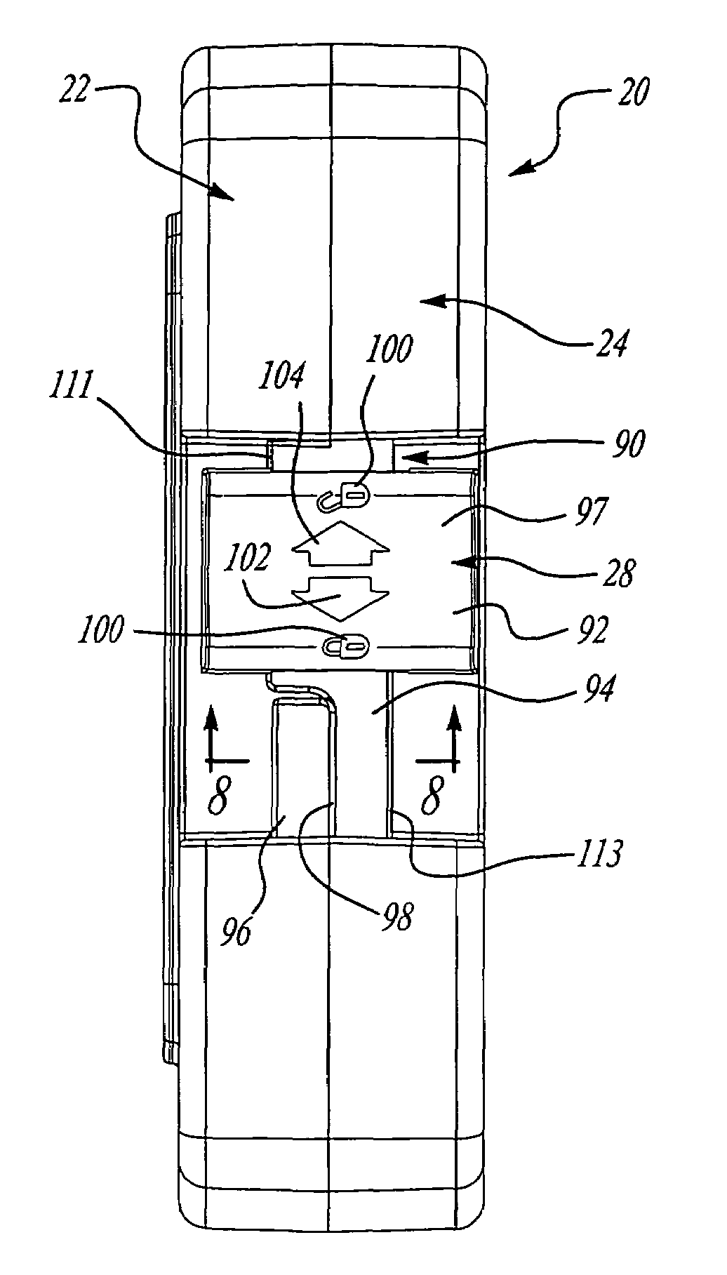
[0007]In accordance with a second aspect of the invention, a latch is provided to retain the housing pairs in locked and unlocked positions. The latch includes a channel defined by an arcuate base surface, a pair of side walls extending from the base, and a pair of flanges extending from the side walls toward one another. The base surface is arcuate along both the longitudinal and lateral axes. One of the flanges includes a cut-out to enhance coupling with the housing pair. The latch includes two sets of indicia, one to indicate a locked and unlocked position, while the other indicates directional movement. The latch is comprised of a first and second member, the first member providing rigidity. A portion of the first member extends through the second member to provide an indicia member. Also, the indicia member is substantially flush with the second member.

Problems solved by technology

While the tool containers work satisfactorily for their designed purpose, these containers have their drawbacks.
One such drawback is some containers are not rugged enough to withstand the day-to-day punishment which a professional user subjects his tools to.
Also, the containers may be large, awkward and difficult to be handled by the user.
Further, the containers may not provide an aesthetic appearance.

Method used


Image

  • Tool container
  • Tool container
  • Tool container

Examples


Embodiment Construction

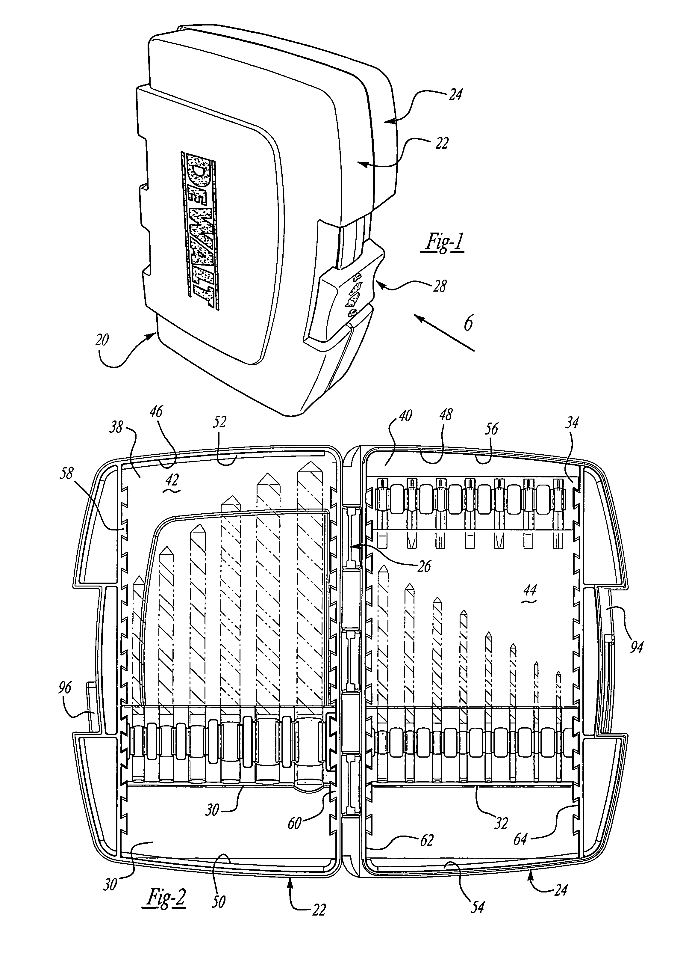
[0039]Turning to the figures, particularly FIG. 1, a tool container is shown and designated with the reference numeral 20. The tool container 20 includes two housing members 22 and 24, which are pivotally secured together by a hinge 26. The housing members 22, 24 also include a locking mechanism 28 to maintain the container 20 in a closed position.

[0040]Turning to FIG. 2, the container 20 is illustrated in an open position. Each half may include one or more tool retaining inserts 30, 32, 34. The tool retaining inserts may retain tool bits or the like, such as drill bits and screwdriver bits.

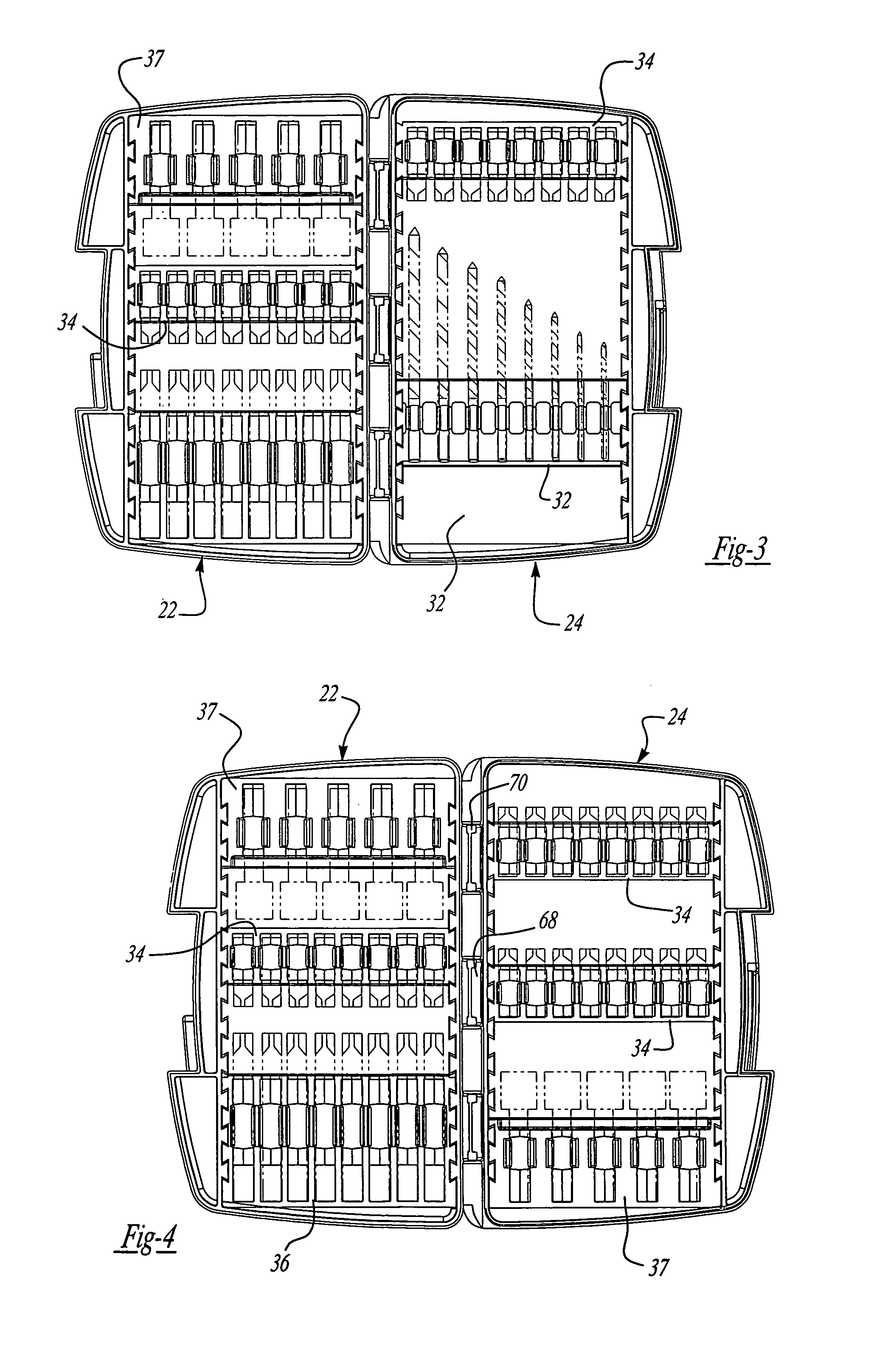
[0041]FIGS. 3 and 4 illustrate embodiments like FIG. 2. Here, inserts 32, 34, 36 and 37 are shown in multiple positions in the housing members 22 and 24. As can be seen, the inserts may be positioned at a plurality of different predetermined positions or orientations in each housing member 22, 24. Any one of the insert and housing mating surfaces enable the accurate positioning and orientating in...


PUM

PropertyMeasurementUnit
Coloraaaaaaaaaa
Stiffnessaaaaaaaaaa

Abstract

A tool container has a pair of housing members pivotally coupled with one another to provide an opened and closed position. At least one of the members defines a cavity to receive tools. The cavity is defined by a base and a wall extending from the base. A tool retaining insert is permanently secured in the cavity. The insert and wall include tenons and grooves to secure the insert in the housing member. Also, an arcuate locking mechanism is included to maintain the pair of housing members in a closed position.

Description

CROSS REFERENCE TO RELATED APPLICATION[0001]This is a divisional of an application filed Aug. 14, 1998 now U.S. Pat. No. 6,755,302 and assigned U.S. Ser. No. 09 / 134,109.BACKGROUND OF THE INVENTION[0002]The present invention relates to tool containers and, more specifically, to containers which include inserts to retain the tools within the container.[0003]Tool users, whether casual or professional, desire to maintain their tools in some type of organized fashion. Tool organization enables a user to readily find the tool, use it, and return it to its place. Thus, several types of tool containers have been provided to serve such a function.[0004]While the tool containers work satisfactorily for their designed purpose, these containers have their drawbacks. One such drawback is some containers are not rugged enough to withstand the day-to-day punishment which a professional user subjects his tools to. Also, the containers may be large, awkward and difficult to be handled by the user. F...

Claims


Application Information

Patent Timeline
IPC IPC(8): A45C13/10E05C1/02A45C5/00A45C13/02B25H3/00B25H3/06E05B65/52
CPCA45C5/00A45C13/02B25H3/003B25H3/021B25H3/023B25H3/06E05B65/5238Y10T24/45168Y10S292/50Y10S292/48Y10T29/49826Y10T24/45005Y10T24/45157Y10T292/096Y10T292/432
Inventor STREICH, JOHN PFINDLE, DANIEL GKEENAN, PATRICK SNAMEY, JR., DAVID
Owner BLACK & DECKER INC
Learn More