Settings of sub-scan feed error and sub-scan feed amount suitable for printing medium

a technology of sub-scan feed and sub-scan amount, which is applied in the field of printing technology, can solve the problems that the accuracy of paper feed according to printing media types has not been taken into account, and achieve the effect of improving image quality

Inactive Publication Date: 2008-01-08
SEIKO EPSON CORP
View PDF17 Cites 1 Cited by
  • Summary
  • Abstract
  • Description
  • Claims
  • Application Information

AI Technical Summary

Benefits of technology

[0011]Since the average feed error δave regarding a specific printing medium is adj

Problems solved by technology

However, the paper feed precision according to types of printing media has not been taken in consideration.

Method used


Image

  • Settings of sub-scan feed error and sub-scan feed amount suitable for printing medium
  • Settings of sub-scan feed error and sub-scan feed amount suitable for printing medium
  • Settings of sub-scan feed error and sub-scan feed amount suitable for printing medium

Examples


first embodiment

C. Setting of feed precision in the

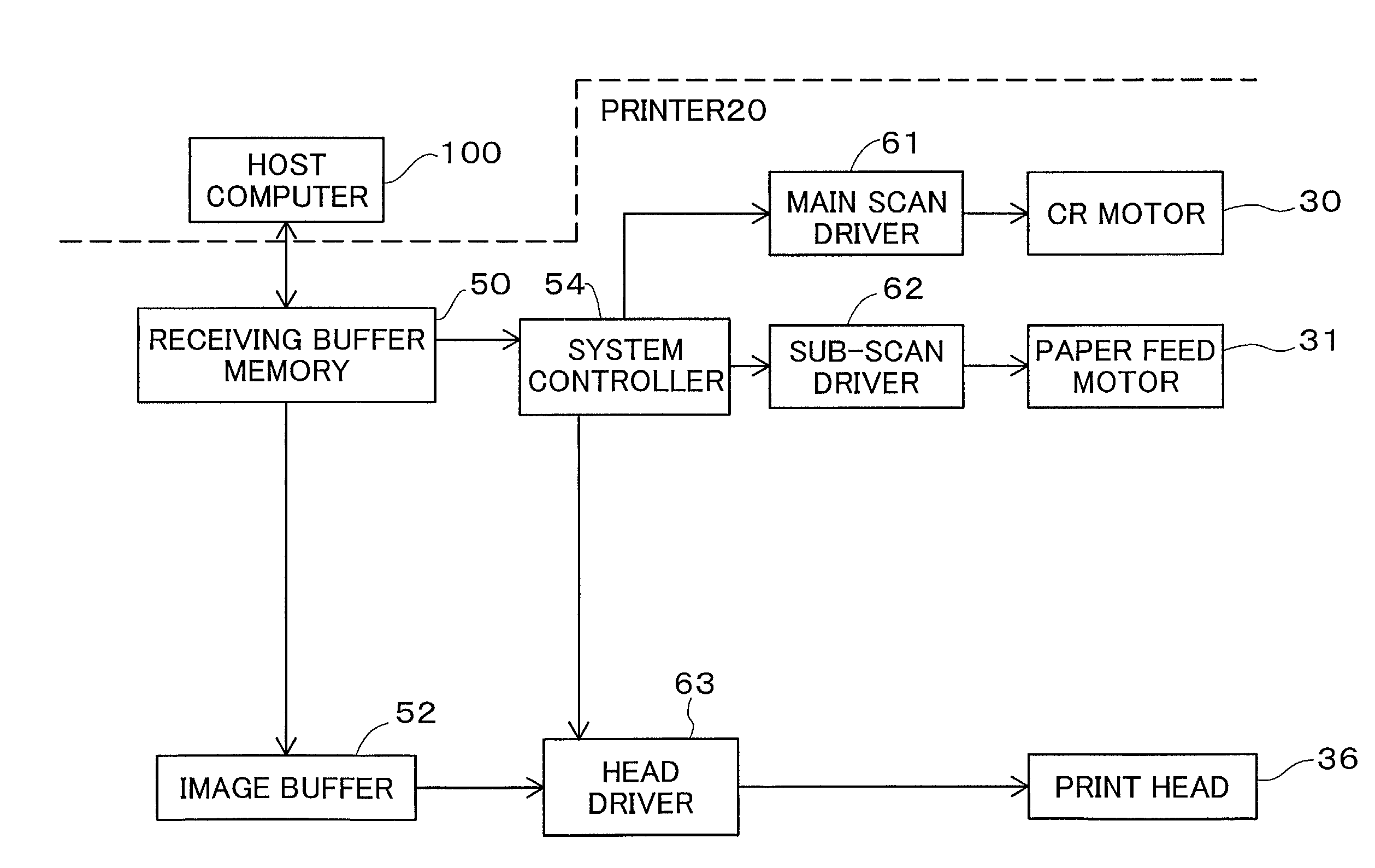
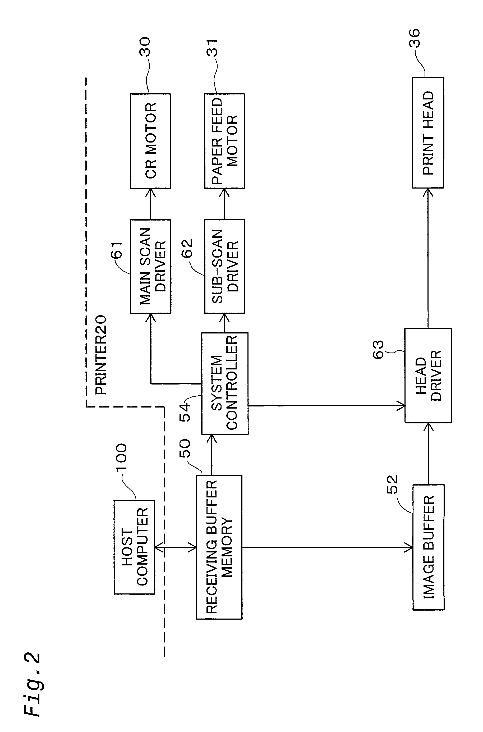
[0056]FIG. 7 is an explanatory diagram showing an user interface of a printer driver displayed on a screen of the host computer 100 (FIG. 2). User can select one printing medium to be actually used from plural types of printing media (also referred to as “printing paper”) designed to be used in this printer 20. The term “plural types of printing media designed to be used in this printer 20” indicates commercially available printing media dedicated for this printer 20.

[0057]FIGS. 8A and 8B are explanatory diagrams showing first example of setting feed errors δ with respect to three types of printing media. FIG. 8A illustrates variance of feed errors δ with respect to three types of printing media, i.e, plain paper, glossy film, and photographic paper. The feed error varies for every sub-scan, but its average is approximately constant. In other words, the average feed error δave is about 15 μm for plain paper, about 8 μm for glossy film, and about 0 ...

second embodiment

D. Feed amount correction in the

[0065]FIGS. 10A and 10B are explanatory diagrams showing feed error δ with respect to three types of printing media used in a comparative example. FIG. 10A illustrates variation of feed errorδ with respect to plain paper, glossy film, and photographic paper. The average feed error δave is about0 μm for plain paper, about −8 μm for glossy film, and about −15 μm for photographic paper. FIG. 10B shows accumulated feed errors Σδ with respect to these printing media.

[0066]In the example shown in FIG. 10A, the sub-scan feed mechanism is adjusted so that among the plural types of printing media designed to be used in the printer 20, average feed error δave of the most unslippery plain paper becomes approximately 0. Moreover, average feed error δave of the other printing media is negative. As for photographic paper, its average feed error δave is a considerably large negative value, which may cause dark banding and degradation of image quality.

[0067]FIGS. 11A...

modification 1

E1. Modification 1

[0078]In the above embodiments, printers that perform “constant feeding” where a constant value is used as sub-scan feed amount is described, but the present invention can also be adopted to printers that perform “variable feeding” where a plurality of different values are used as sub-scan feed amount.


PUM


Abstract

A printing device comprises a feed mechanism configured to advance the printing medium intermittently. The feed mechanism is adjusted so that an average feed error δave is in the vicinity of zero with respect to a most slippery printing medium among plural types of printing media designed to be used in the printing device. Alternatively, a printing device comprises a controller to correct a feed amount such that an average feed error δave is in the vicinity of zero with respect to at least one specific printing medium among plural types of printing media designed to be used in the printing device.

Description

BACKGROUND OF THE INVENTION[0001]1. Field of the Invention[0002]The present invention relates to a printing technology for recording an image onto a printing medium.[0003]2. Description of the Related Art[0004]Ink jet printers and laser printers are widely used as computer output devices. Particularly, color printers are prevailing in recent years. Since color reproducibility of ink significantly depends on types of printing media, printer manufacturers provide various types of printing media suitable for color printing.[0005]The type of printing medium has effect not only on the color reproducibility of ink, but also on precision of feeding printing medium (referred to as “paper feed” hereinafter). For example, paper feed operation for a printing medium with a slippery surface and the same operation for a printing medium with an unslippery surface may sometimes result inconsiderably different actual feed amounts.[0006]Image quality is greatly affected by feed precision. However, th...

Claims


Application Information

Patent Timeline
IPC IPC(8): G06F15/00B41J13/00
CPCB41J13/0027
Inventor OTSUKI, KOICHI
Owner SEIKO EPSON CORP
Why Eureka
Try Eureka