
Fishing pole with integrated line tension scale

a technology of fishing poles and tension scales, applied in the field of fishing pole design, can solve the problems of difficult approach, impracticality of both approaches, and difficulty in using the average fisherman, and achieve the effect of constant measurement and display of fishing line tension

Inactive Publication Date: 2008-01-15
LRP
View PDF14 Cites 9 Cited by
  • Summary
  • Abstract
  • Description
  • Claims
  • Application Information

AI Technical Summary

Benefits of technology

[0010]Accordingly, the present invention, a fishing pole with integrated line tension measuring device, measures the fishing line tension at all times without any ancillary apparatus. The invention provides the constant measurement and display of fishing line tension in quantitative units, e.g. pounds or kilograms. Using the invention, the user can monitor the fishing line tension applied by the drag precisely both before fishing, and more importantly, while a fish is being fought. The invention allows the fisherman to adjust the drag and view the resulting line tension change immediately.

Problems solved by technology

In the field of sport fishing, the desire for a proper drag setting is a continuing, yet unsatisfied goal.
Both approaches are impractical and not used by the average fisherman.
This approach is difficult and requires the fisherman to carry this extra apparatus with him.
While this device may actually produce a quantifiable measurement, the circuitry involved is relatively complex and would be correspondingly expensive.
Fishing reels are already one of the more significant expenses in fishing and purchasing new reels with this type of mechanism would be very expensive.
Those skilled in the art realize that threading the fishing line through any device adversely impacts its practical application for fishing.
Any additional routing of the fishing line through measuring apparatus will adversely impact both casting, where the line must run free and unimpeded from the reel, and fishing, where the fisherman needs the line sensitivity to feel the bait swimming and the target fish biting.
Additionally, the amount of drag applied by a reel may change as the drag mechanism heats or cools or binds.
It is currently impossible to know the actual line tension when fighting a fish.
It is also impossible to know accurately how the line tension changes when adjusting the drag while fighting a fish.

Method used


Image

  • Fishing pole with integrated line tension scale
  • Fishing pole with integrated line tension scale
  • Fishing pole with integrated line tension scale

Examples


Embodiment Construction

[0024]Many of the figures describing the preferred embodiments of the inventions show a fishing reel for illustrative purposes. The fishing reel itself is not part of the invention.

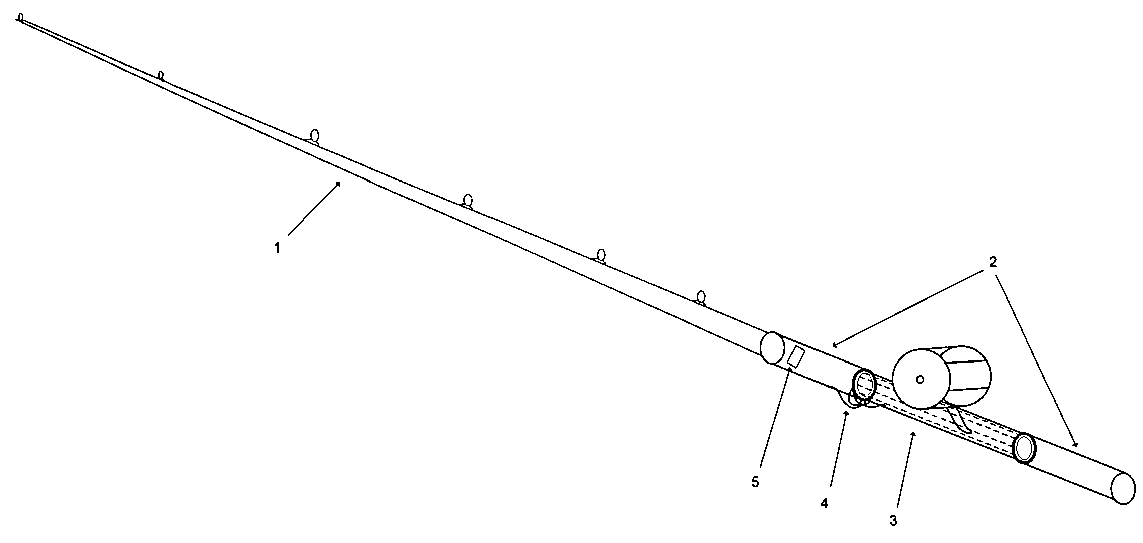
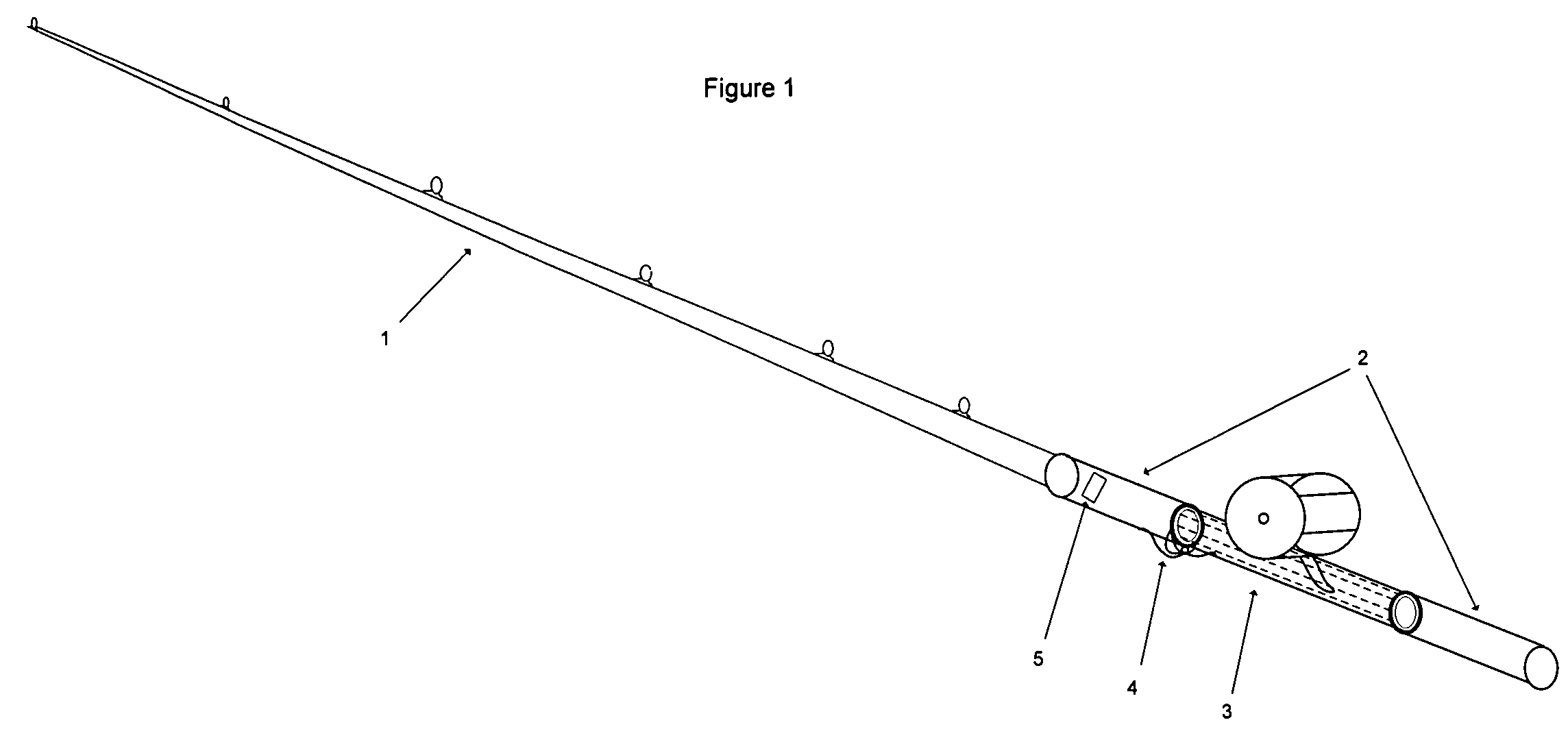
[0025]FIG. 1 is a perspective view showing the preferred embodiment of the fishing pole with integrated line tension measuring device according to the invention. A fishing pole consists of a rod (1) and handle (2). The rod extends all the way through the center of the handle to the base of the fishing pole. A reel seat (3), or place to connect the reel, is commonly situated in the center section of the handle. In this embodiment, the line tension measuring device (4) and line tension display (5) are integrated into the handle portion of the fishing pole.

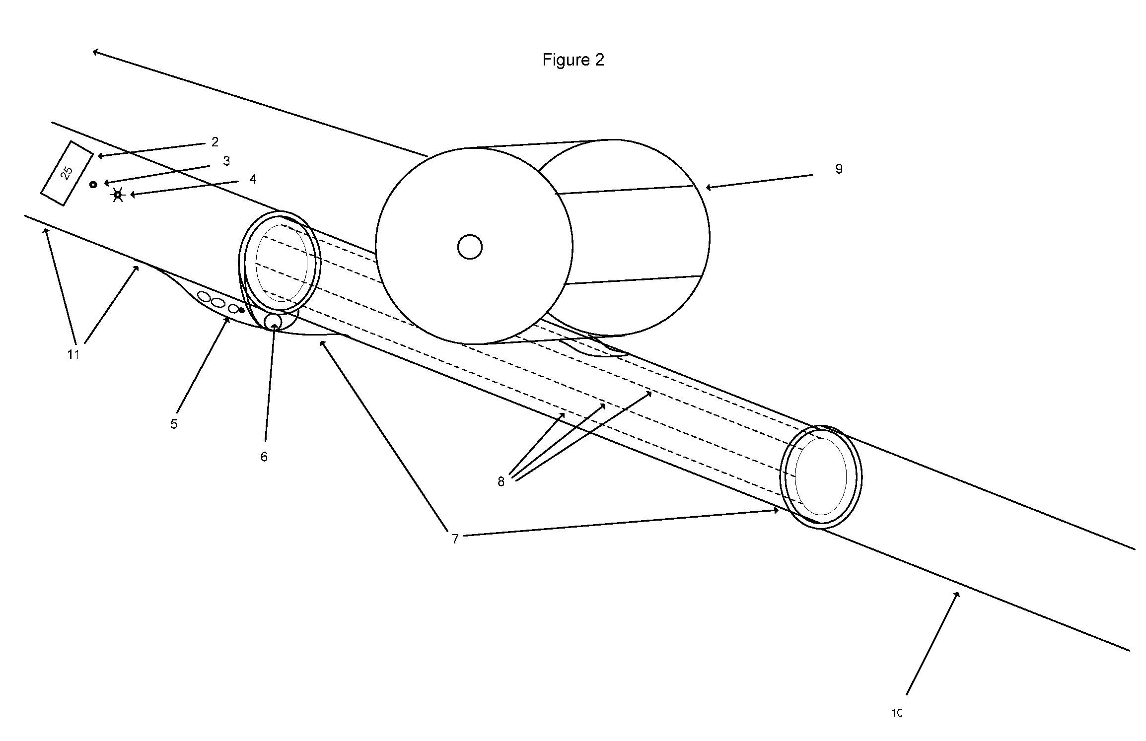
[0026]FIG. 2 is a perspective view detailing the handle portion of the preferred embodiment of the fishing pole with integrated line tension measuring device according to the invention. The handle consist of the forward grip (11), a sliding reel mount (7),...


PUM


Abstract

The invention is a fishing pole with an integrated line tension measuring device. Measured line tension is displayed in quantitative units, pounds or kilograms. A line tension warning system activates when the sensed line tension exceeds a threshold set by the fisherman. The line tension measuring device does not touch the fishing line so the fishing pole with integrated line tension measuring device fishes and operates like a normal fishing pole. The line tension measuring device may be integrated into the fishing reel seat which, in turn, is an integral part of the fishing pole.

Description

[0001]The invention is a fishing pole with an integrated line tension measuring device. Measuring fishing line tension or “drag” has always been subjective. Most often a fisherman pulls on the line by hand and adjusts the drag, or braking force on the reel, based on what the pull ‘feels’ like. While fighting a fish, it is difficult to know how hard the fish is pulling on the line. The invention, a fishing pole that measures and displays the actual pull on the line in quantitative units, e.g. pounds or kilograms, enables the fisherman to accurately set the drag and know how hard a fish is pulling on the line. The line tension is measured and displayed continuously, thereby enabling the fisherman to accurately adjust the drag even when fighting a fish.FIELD OF INVENTION[0002]This invention applies to the field of fishing and more particularly to the design of fishing poles.DISCUSSION OF PRIOR ART[0003]In the field of sport fishing, the desire for a proper drag setting is a continuing,...

Claims


Application Information

Patent Timeline
Patent Type & Authority Patents(United States)
IPC IPC(8): A01K97/12
CPCA01K87/007A01K87/06A01K97/125
Inventor PEKIN, DAVID
Owner LRP
Learn More