Arc fault detection apparatus, method and system for an underground electrical conductor

a technology of underground electrical conductors and fault detection equipment, applied in emergency protective arrangements, circuit breaking switches, instruments, etc., can solve problems such as power loss, arc faults, overload capability of circuit breakers that will not function,

Active Publication Date: 2008-01-15
EATON INTELLIGENT POWER LTD
View PDF25 Cites 74 Cited by
  • Summary
  • Abstract
  • Description
  • Claims
  • Application Information

AI Technical Summary

Problems solved by technology

Arc faults can be caused, for instance, by worn insulation between adjacent bared conductors, by other insulation failures and in other situations where conducting elements are in close proximity.
Arcing faults between two conductors can also result from an over the surface conductive path forming on an insulator caused by, for example, salt water.
During sporadic arc fault conditions, the overload capability of a circuit breaker will not function since the root-mean-squared (RMS) value of series arc fault current pulses is too small to activate the thermal based automatic trip circuit.
These explosions cause a loss of power in the aftermath and, moreover, provide a risk of injury.
For example, underground power cables can become frayed from aging, from corrosive chemicals (e.g., road salt), from overload or from vermin biting them.
However, the limiters do not respond to an insulation related arc fault because the current's RMS value is too low.
It is believed that network relays cannot be employed as suitable protectors either, since the network relays cannot detect the relatively low level arcing current, much less identify the location of the arc fault.
If a protector cannot locate the fault, even if it knew there was a fault, it would not be advisable to open the protector since a relatively large geographic area would be without power.
Also, once the network is deenergized, the smoke from the fault would cease and, thus, the fault could not be located.
As the arcing heats the cable insulation, the insulation smolders and releases flammable gases.
The arcing, also, may ignite the insulation and / or the gases, which can cause a powerful explosion.
However, these slotted manhole covers cannot be used in locations where run off from a rainstorm could result in manhole flooding.
Furthermore, such underground problems can go undetected until a smoking manhole is reported.
This may take time and money and, moreover, may subject the crew to dangerous conditions.

Method used


Image

  • Arc fault detection apparatus, method and system for an underground electrical conductor
  • Arc fault detection apparatus, method and system for an underground electrical conductor
  • Arc fault detection apparatus, method and system for an underground electrical conductor

Examples


example 1

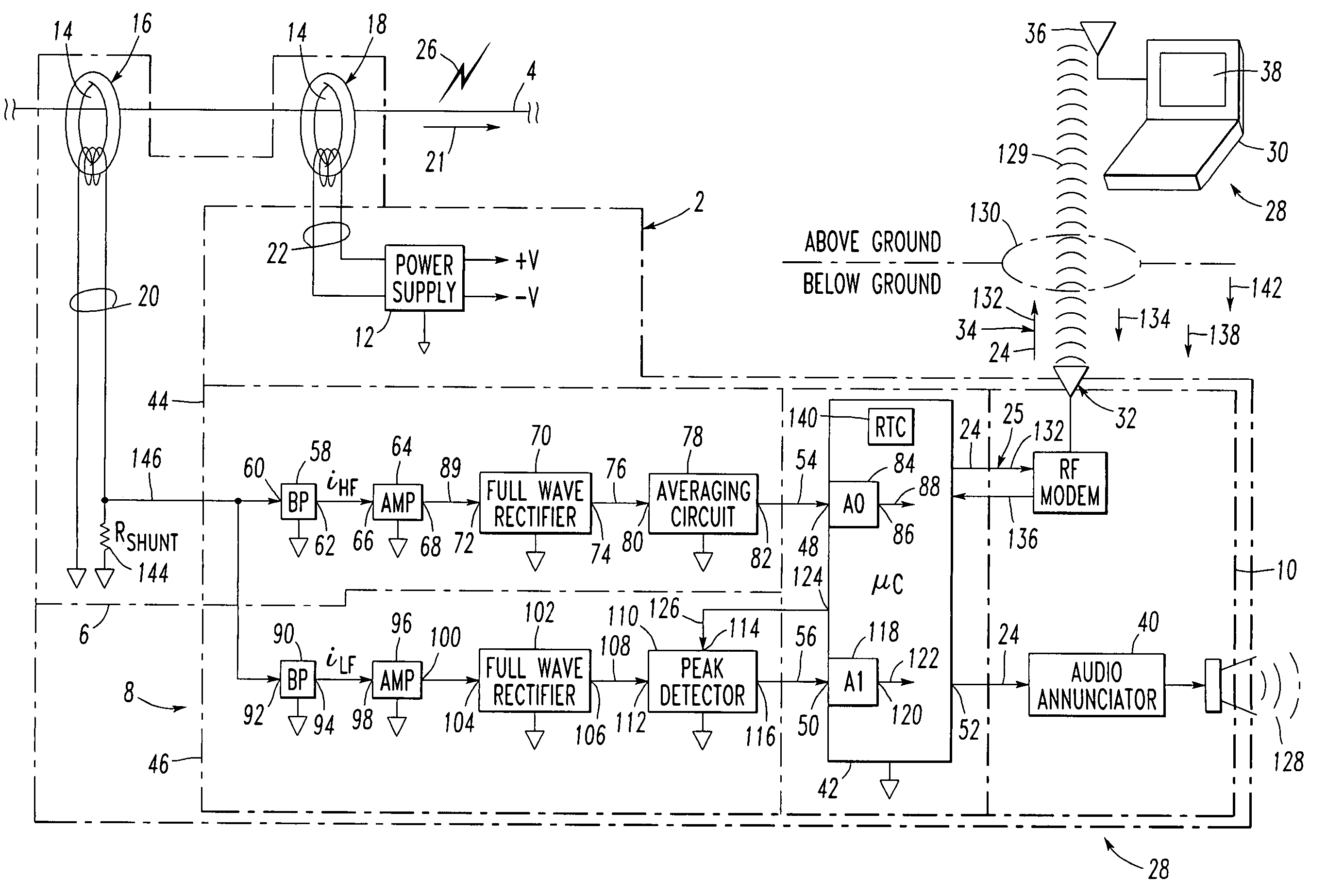
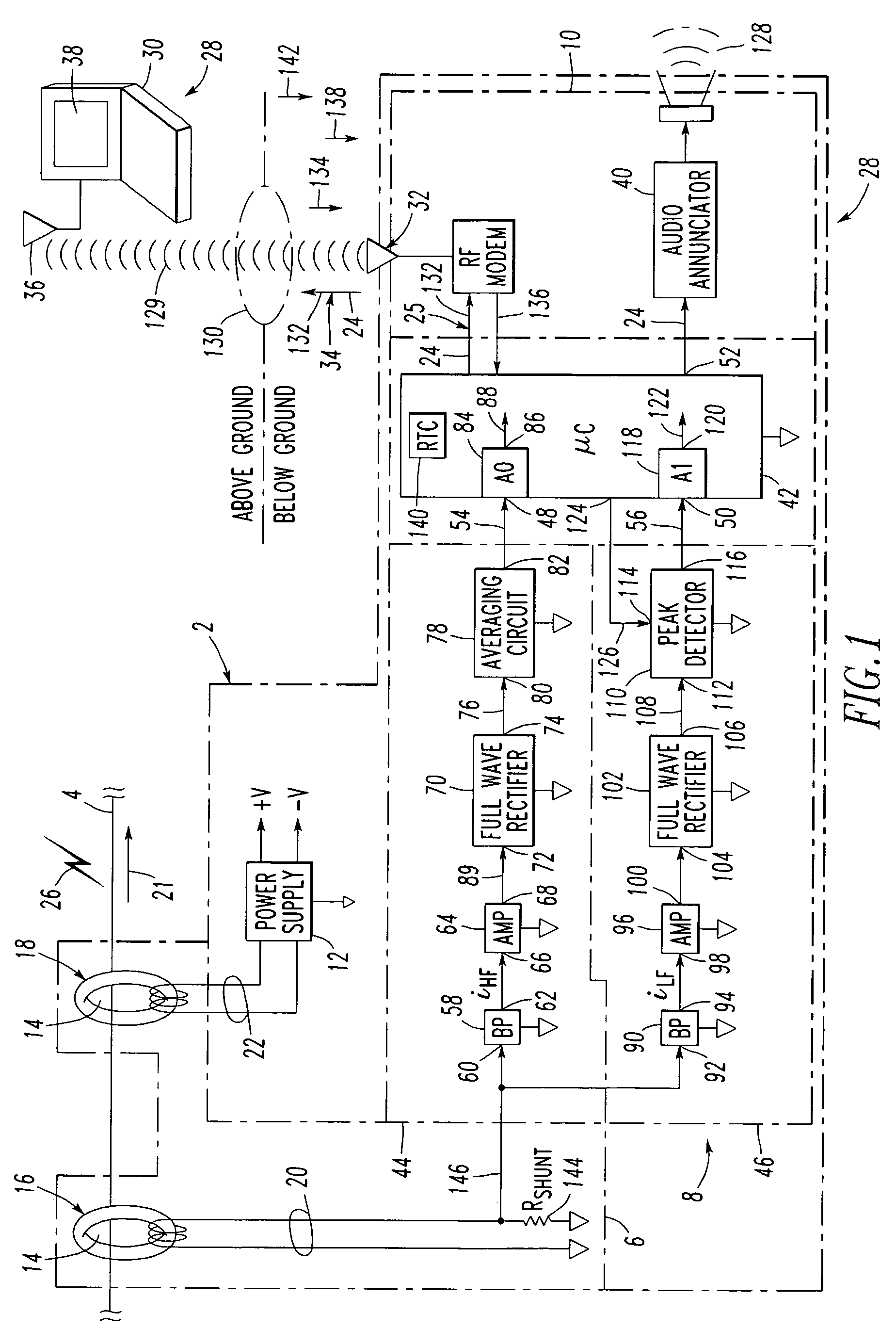
[0036]The example arc fault detection circuit 8 includes a suitable processor, such as a microcomputer (μC) 42 and two input circuits 44,46. The μC 42 includes a first input 48, a second input 50 and an output 52. The first circuit 44 inputs the first signal 20 and outputs a fourth signal 54 to the first μC input 48. The second circuit 46 also inputs the first signal 20 and outputs a fifth signal 56 to the second μC input 50. The μC 42 is adapted to output on the output 52 the third signal 24, which is representative of the arc fault 26 and which is derived from the fourth and fifth signals 54,56, as will be described.

[0037]Numerous characteristics of an arc fault, such as 26, caused by an insulation failure of the electrical conductor 4 may be recognized. Two example characteristics are employed by the first (high frequency) input circuit 44 and the second (low frequency) input circuit 46 of FIG. 1. Both of these circuits 44,46 employ the instability of the arcing current as an ind...

example 2

[0045]Preferably, the audio annunciator 40 (e.g., without limitation, a Piezoelectric transducer) is employed. The output audio signal 128 is important since the arc fault detector / alarm circuit 2 is typically mounted underground. Hence, practical mechanisms for reporting an arcing event are limited. The audio signal 128 may be reported, for example, by a passing citizen or by regular inspections by a maintenance crew of a power distribution entity, as will be discussed. In this example, the arc fault detector / alarm circuit 2 is suitably adapted to be mounted underground with the underground electrical conductor 4.

example 3

[0046]The output audio signal 128 may be suitably modulated by the μC 42 at output 52 by employing a suitable amplitude or intensity, a suitable frequency or tone, and / or a suitable pulse rate modulating pattern. The modulation may be employed to indicate information such as, for example, arcing amplitude (e.g., as determined from the peak value or fifth signal 56 as output by the peak detector circuit 110) and / or count of arcing occurrences (e.g., the arcing may be intermittent and may occur in spurts over a relatively long time).


PUM


Abstract

A non-invasive underground arc fault detection apparatus is for an underground electrical conductor. The apparatus includes an electric circuit having an opening for admitting the electrical conductor therethrough. The electric circuit includes one or two transducers adapted to output a first signal representative of current flowing in the electrical conductor and a second signal. An arc fault detection circuit cooperates with the electric circuit to output a third signal derived from the first signal. The third signal is representative of an arc fault of the electrical conductor. An audible annunciator cooperates with the arc fault detection circuit to annunciate the third signal. A power supply cooperates with the electric circuit and is adapted to power the arc fault detection circuit and the annunciator from the second signal.

Description

BACKGROUND OF THE INVENTION[0001]1. Field of the Invention[0002]This invention pertains generally to detection and annunciation apparatus and, more particularly, to such an apparatus for detecting and annunciating arc faults. The invention also relates to methods and systems for detecting and annunciating arc faults.[0003]2. Background Information[0004]Arcing is a luminous discharge of electricity across an insulating medium, usually accompanied by the partial volatilization of electrodes. An arc fault is an unintentional arcing condition in an electrical circuit, such as an electrical conductor. Arc faults can be caused, for instance, by worn insulation between adjacent bared conductors, by other insulation failures and in other situations where conducting elements are in close proximity. Arc faults in systems can be intermittent since the magnetic repulsion forces generated by the arc current force the conductors apart to extinguish the arc. Mechanical forces then bring the conduc...

Claims


Application Information

Patent Timeline
Patent Type & Authority Patents(United States)
IPC IPC(8): H02H3/00G08B3/00H02H3/10H04B5/00
CPCH02H1/0015H02H3/04H02H7/228
Inventor ENGEL, JOSEPH C.
Owner EATON INTELLIGENT POWER LTD
Why Eureka
Try Eureka