
Fire rated recessed lighting assembly

a technology for recessed lighting and assembly, which is applied in the direction of fixed installation, lighting and heating equipment, transportation and packaging, etc., can solve the problems of changing the fire safety rating of the floor-ceiling assembly, the floor-ceiling assembly may no longer meet certain ul fire safety standards, and the structure is severe damaged or total loss

Active Publication Date: 2008-01-22
ABL IP HLDG
View PDF5 Cites 96 Cited by
  • Summary
  • Abstract
  • Description
  • Claims
  • Application Information

AI Technical Summary

Problems solved by technology

However, one problem associated with installing a recessed lighting assembly in such a manner is that the hole cut in the surface can change the UL fire safety ratings of the floor-ceiling assembly as a result of the ceiling structure being breached.
For or example, by cutting a hole into the ceiling, a non-continuous surface results and the floor-ceiling assembly may no longer satisfy certain UL fire safety standards.
Allowing either flame, heat or both to enter the space above the floor-ceiling assembly may cause severe damage or total loss of the structure.
However, because the fire box is unattached and must be fabricated by the installer separately from the lighting assembly, a substantial amount of additional time, materials and expense can be incurred.
Moreover, because most builders are unsure of the minimum size box to provide sufficient fire safety, exceedingly large boxes are typically utilized, causing unnecessary cost and expense.
These prefabricated enclosures, however, are also often larger than necessary to enclose the recessed lighting assembly, causing unnecessary costs to be incurred.
However, the cost of these conventional preassembled recessed light fixtures is typically very high due to the labor and material expense required to fabricate the drywall panel walls and support structure or to stamp and coat all internal surfaces.
In addition, the weight of each of these conventional preassembled recessed light fixtures increases the difficulty of installing the respective recessed lighting assembly.

Method used


Image

  • Fire rated recessed lighting assembly
  • Fire rated recessed lighting assembly
  • Fire rated recessed lighting assembly

Examples


Embodiment Construction

[0021]Reference will now be made in detail to an implementation consistent with the present invention as illustrated in the accompanying drawings. Wherever possible, the same reference numbers will be used throughout the drawings and the following description to refer to the same or like parts. As would be understood to one of ordinary skill in the art, certain components or elements for installation of a recessed light fixture (e.g., building support members, hanger arms, junction box, or electrical connections) are not shown in the figures or specifically noted herein to avoid obscuring the invention.

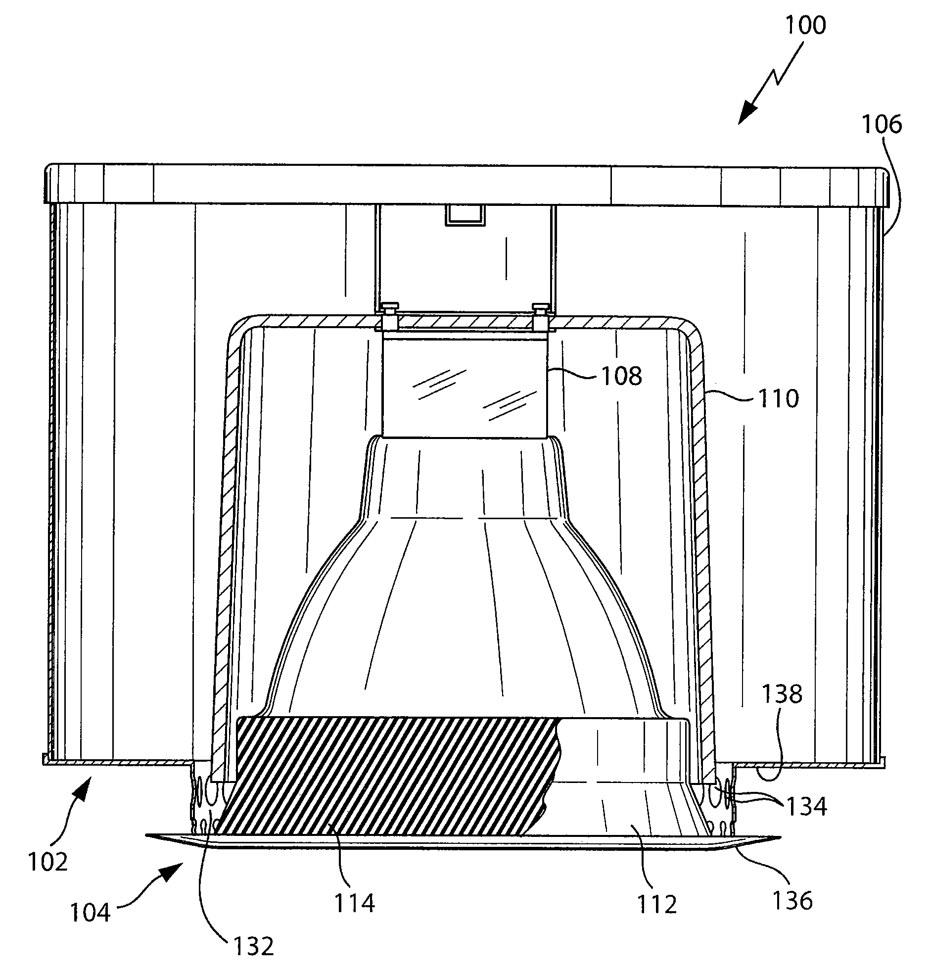
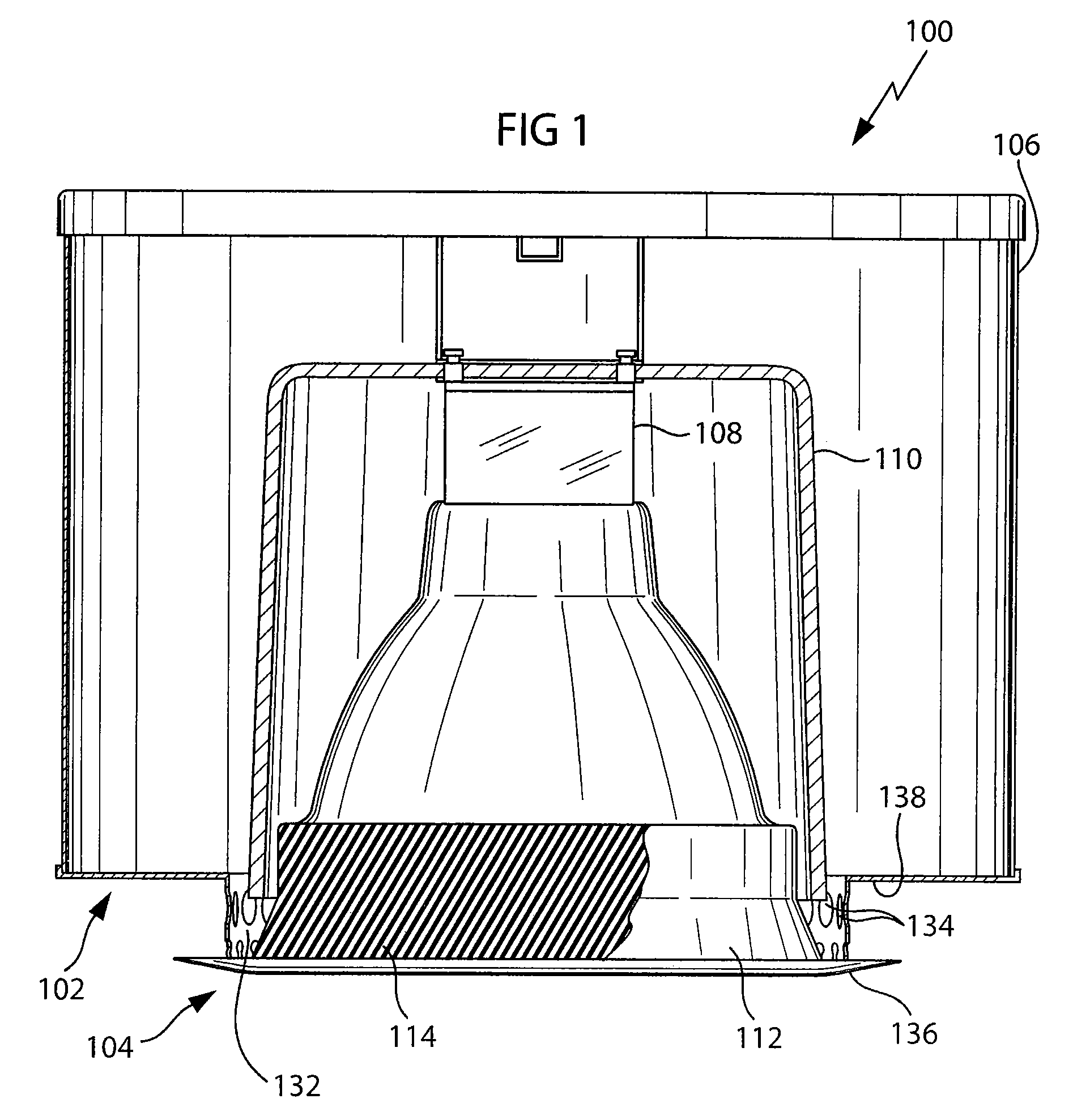
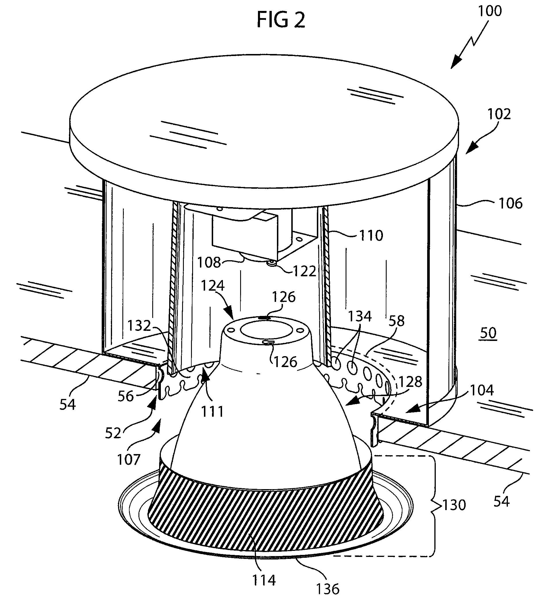
[0022]FIGS. 1-4 depict one embodiment of a lighting assembly 100 consistent with the present invention. The lighting assembly 100 includes a light fixture 102 and a trim 104 adapted to mate with or be installed on the light fixture 102. The trim 104 may have a cylindrical shape, a conical shape, or another shape adapted to allow light out of the light fixture. The trim 104 may include...


PUM


Abstract

A lighting assembly that includes a light fixture adapted to be disposed in relation to an opening defined in a surface of a structure such that a lamp may be installed in the light fixture through the opening, a trim having an outer surfaces, and an intumescent layer on the outer surface of the trim. The trim is adapted to engage the light fixture so that the outer surface of the trim on which the intumescent layer is disposed is positioned in proximity to the opening in the structure. The intumescent layer is adapted to expand to form a fire resistant seal between the trim and the structure when the intumescent layer reaches a predetermined temperature.

Description

FIELD OF THE INVENTION[0001]The invention relates to a lighting assembly and, more particularly, to a fire rated lighting assembly that, when installed in a ceiling, floor, or wall structure of a room, inhibits a fire in the room from traveling through the structure via the recessed lighting assembly.BACKGROUND OF THE INVENTION[0002]Current residential and commercial buildings must generally comply with certain fire safety standards such as set forth by Underwriters Laboratories (UL), National Fire Protection Association (NFPA), or other administrative agency. For example, wood joists and sheet rock are typically used to create a finished room in a residential or commercial building. When using such materials, the building room or structure must typically satisfy a specific UL “fire-rated” assembly standard. For example, one applicable test is UL's 1 hr. Fire Rated L-500 Floor-Ceiling Assembly test. This test measures and rates a given floor-ceiling assembly for fire safety complian...

Claims


Application Information

Patent Timeline
Patent Type & Authority Patents(United States)
IPC IPC(8): F21V17/00
CPCF21S8/02F21V25/00
Inventor PETRAKIS, JOHNO'BRIEN, AARON
Owner ABL IP HLDG
Learn More