Polyaxial bone screw with split retainer ring

a bone screw and retainer ring technology, applied in the field of bone screws, can solve the problems of not always being able to insert a bone, difficult to feed long rods through closed head screws, and inability to fit many parts, etc., and achieves the effects of convenient and secure use, good adaptability, and economics

Active Publication Date: 2008-01-29
JACKSON
View PDF41 Cites 185 Cited by
  • Summary
  • Abstract
  • Description
  • Claims
  • Application Information

AI Technical Summary

Problems solved by technology

Open head screws are most often used, mainly because it is difficult to feed long rods through closed head screws.
When the head and shank of the bone screw are fixed in position relative to each other, it is not always possible to insert a bone screw into the bone in such a manner that the head will be in the best position for receiving other implants.
Unfortunately, the prior art devices have a tendency to be bulky, slip under high loading or require many parts.
As noted above, many prior art swivel type bone screws have a bulky and heavy structure.

Method used


Image

  • Polyaxial bone screw with split retainer ring
  • Polyaxial bone screw with split retainer ring
  • Polyaxial bone screw with split retainer ring

Examples


Embodiment Construction

[0024]As required, detailed embodiments of the present invention are disclosed herein; however, it is to be understood that the disclosed embodiments are merely exemplary of the invention, which may be embodied in various forms. Therefore, specific structural and functional details disclosed herein are not to be interpreted as limiting, but merely as a basis for the claims and as a representative basis for teaching one skilled in the art to variously employ the present invention in virtually any appropriately detailed structure.

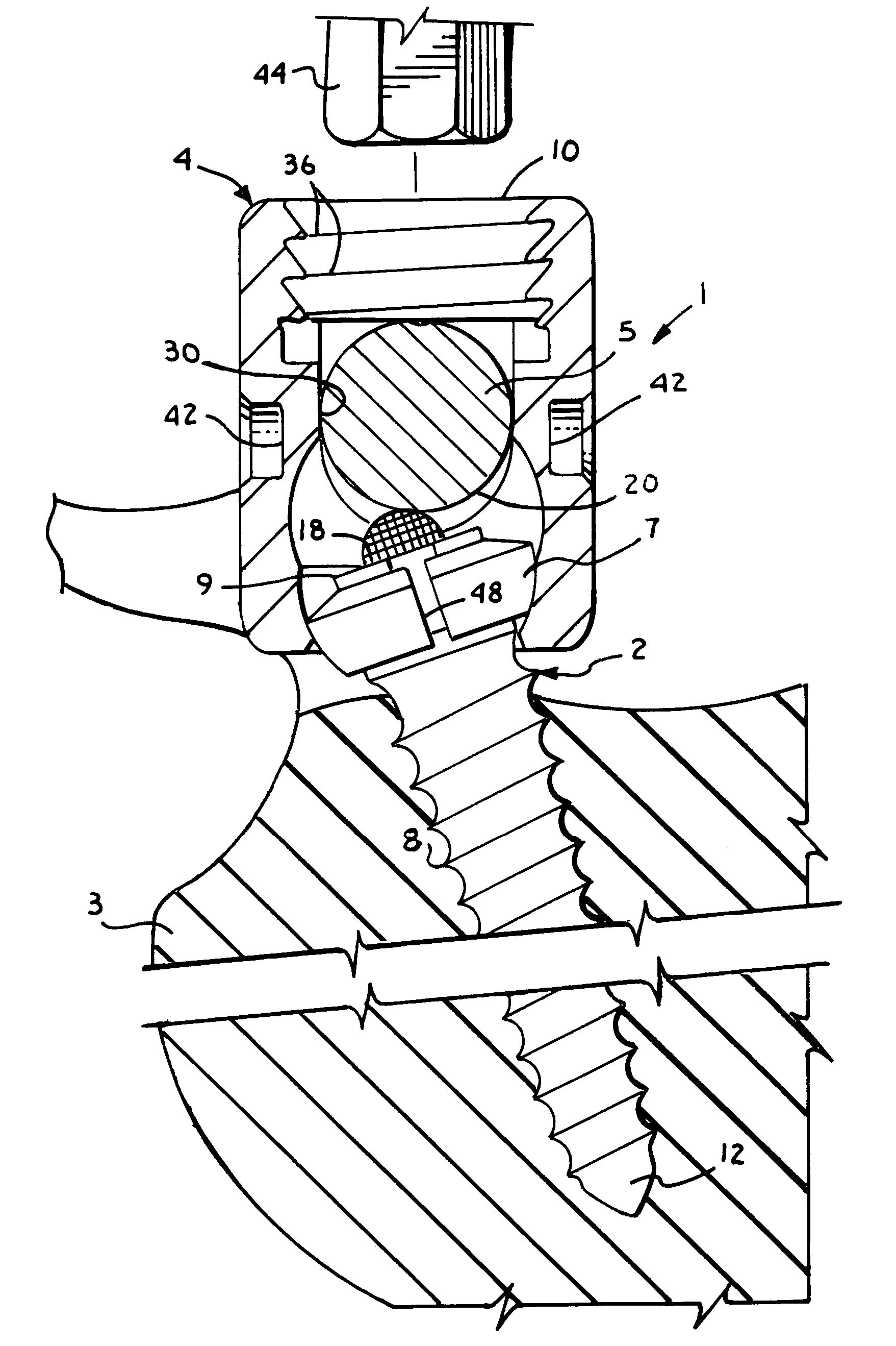
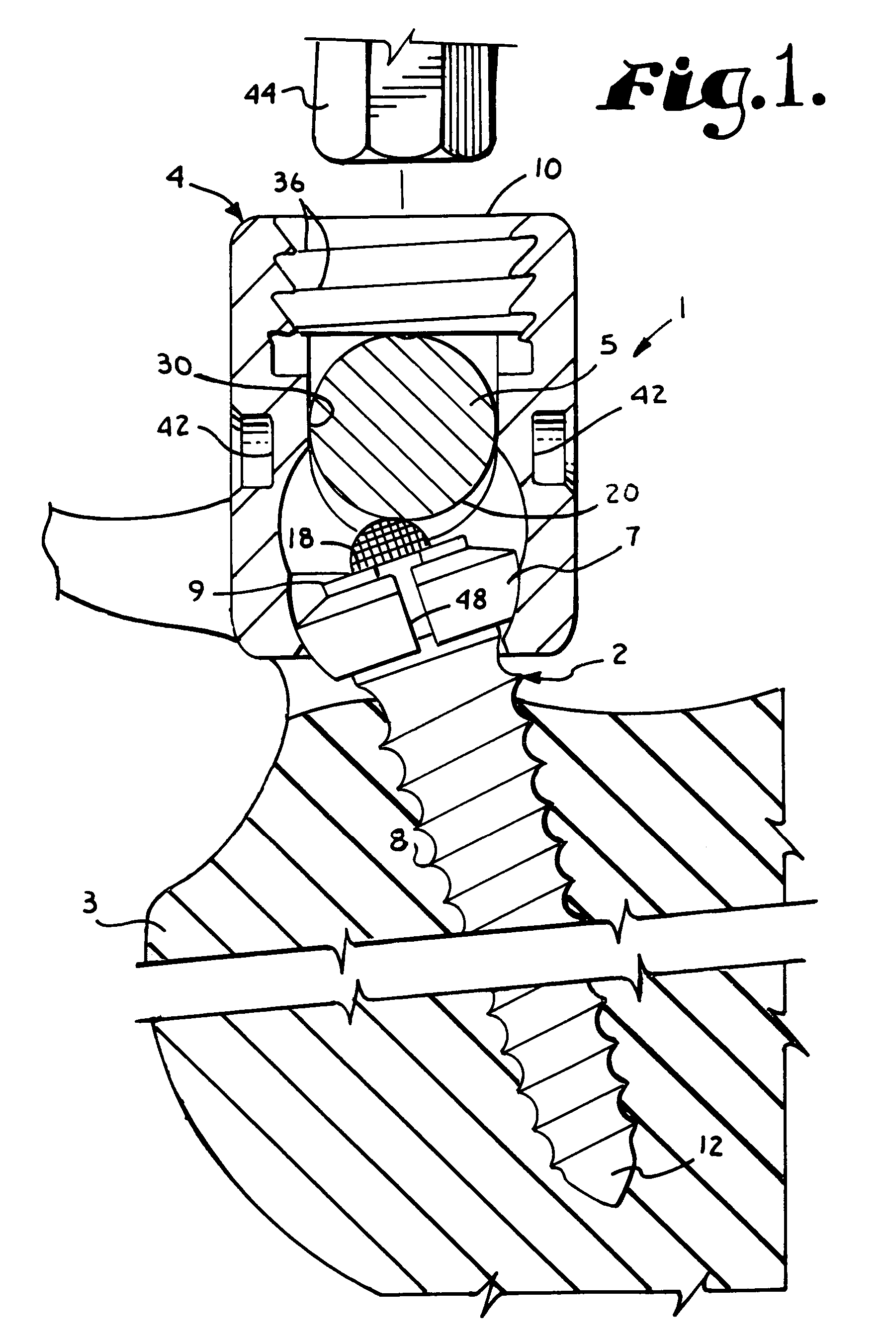
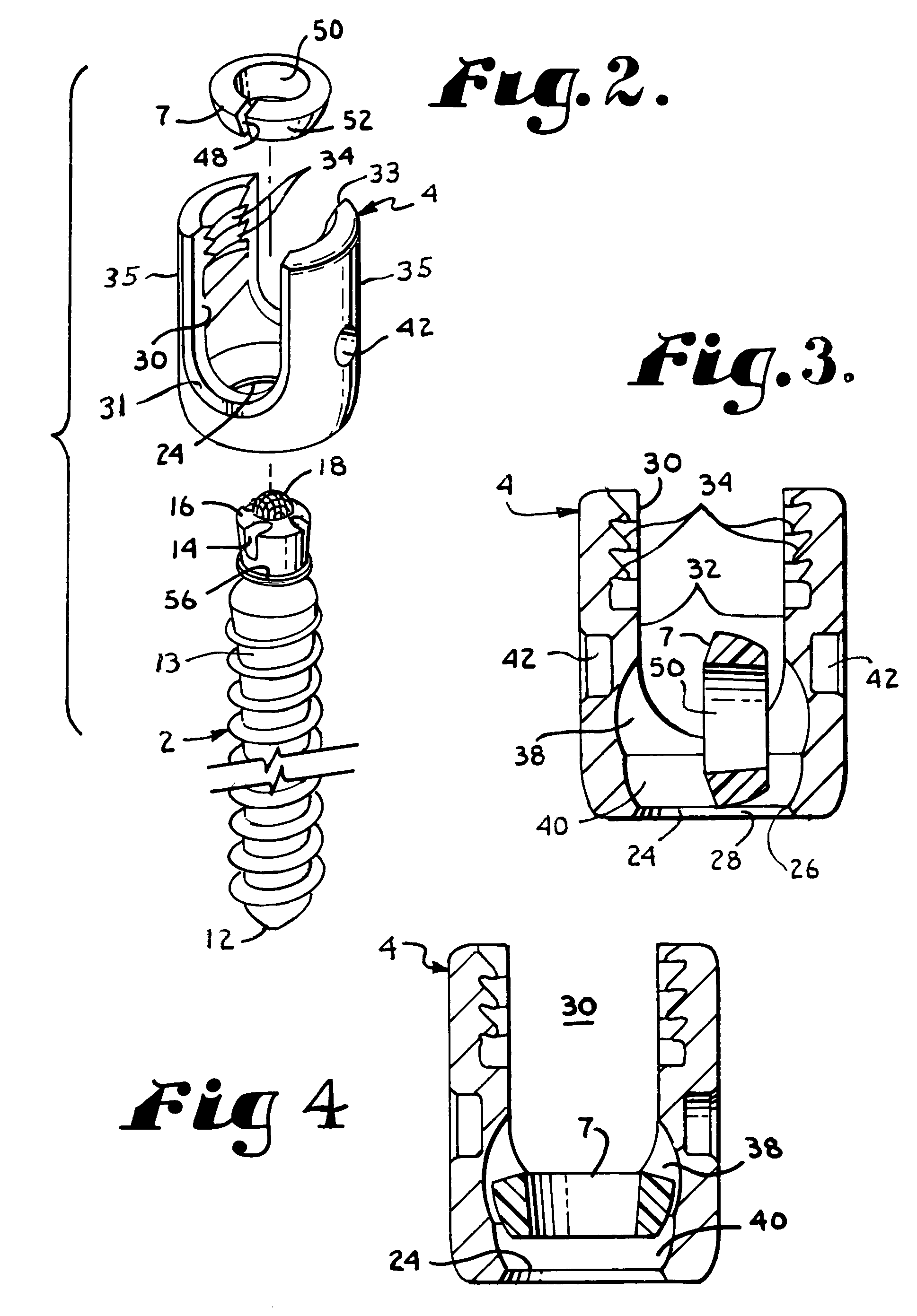
[0025]Referring to the drawings in more detail, the reference numeral 1 generally designates a polyaxial bone screw arrangement which embodies the present invention. The arrangement 1 includes a threaded shank member 2 for threadably implanting into a bone 3, such as a vertebra, and a head member 4 which connects with the shank member 2 to engage and secure a rod member 5, such as a spinal fixation rod, relative to the bone 3. The arrangement 1 also includes ...


PUM


Abstract

A polyaxial bone screw includes a head member and a shank member. The shank has a capture end and an opposite threaded end for threaded insertion into a vertebra. The head has a U-shaped cradle for receiving a spinal fixation rod and a central bore for receiving the capture end of the shank. An expandible retainer ring with a radial split is snapped onto the capture end of the shank to retain it within the head. The retainer ring has a spherical outer surface which forms a ball joint with a spherical socket cavity within the head to enable the head to be angled relative to the shank. A threaded closure plug is tightened within the cradle to clamp the rod into engagement with a knurled dome on the capture end of the shank to secure the rod relative to the vertebra.

Description

BACKGROUND OF THE INVENTION[0001]The present invention is directed to a bone screw of the type wherein a head of the bone screw is swingable or can swivel about the shank of the bone screw until the surgeon is satisfied with the relative placement of the two parts and thereafter the head can be locked in position relative to the shank. Such screws are also referred to as polyaxial head or swivel head bone screws, since the head can be positioned in any of a number of angular configurations relative to the shank.[0002]Bone screws are advantageously utilized in many types of spinal surgery in order to secure various implants to vertebrae along the spinal column. Bone screws of this type typically have a shank that is threaded and adapted to be implanted into a vertebral body of a vertebra. The bone screw includes a head which is designed to extend beyond the vertebra and which has a channel to receive another implant. Typically the channel will receive a rod or a rod-like member. In b...

Claims


Application Information

Patent Timeline
Patent Type & Authority Patents(United States)
IPC IPC(8): A61B17/70
CPCA61B17/7037A61B17/7032
Inventor JACKSON, ROGER P.
Owner JACKSON
Why Eureka
Try Eureka