Surgical saw for cutting off cheek bones

a surgical saw and cheek bone technology, applied in the field of surgical saws for cutting off cheek bones, can solve the problems of requiring a lot of time, affecting and causing the appearance of the face to be deteriorated, so as to achieve the effect of reducing the safety of patients, and reducing the risk of fractur

Inactive Publication Date: 2008-01-29
LEE JAE HWA
View PDF13 Cites 19 Cited by
  • Summary
  • Abstract
  • Description
  • Claims
  • Application Information

AI Technical Summary

Benefits of technology

[0011]Further, the left and right sides of the spacing members and the both sides of the front end portion of the arm, which are closely contacted with each other, have up-and-down movement preventing structures for preventing the individual saw blades from relative rotations with respect to the arm by restraining relative movements in up-and-down directions with respect to each other and movements in up and down directions of the individual saw blades.

Problems solved by technology

Appropriate cheek bone bulges give a vigorous and good look and a three-dimensional effect, but excessive cheek bone bulges cause a face to look wide and a nose to look relatively low in front view so that the bulges may be a factor for a face appearance to be deteriorated.
Particularly, the excessive bulges together with a square chin which is distinctly protruded and angled cause a strong and rough appearance so that they give an adverse feeling to others.
However, in case that the conventional surgical saw for cutting off cheek bones as mentioned above is used, the saw portion 12 has only one saw blade so that at least two times cutting operations are needed to partially cut off cheek bones, as shown in FIG. 3, causing a problem that surgeries become very cumbersome as well as require lots of time.
Further, a cutting interval has to be adjusted based on naked eyes through the skin opened by cutting, so that it is very difficult to adjust cutting-off widths of both individual cheek bones of a face due to a difficult securing of a visual field, causing a high occurrence frequency of surgery aftereffects bringing an asymmetry of the left and right sides of a face.

Method used


Image

  • Surgical saw for cutting off cheek bones
  • Surgical saw for cutting off cheek bones
  • Surgical saw for cutting off cheek bones

Examples


Embodiment Construction

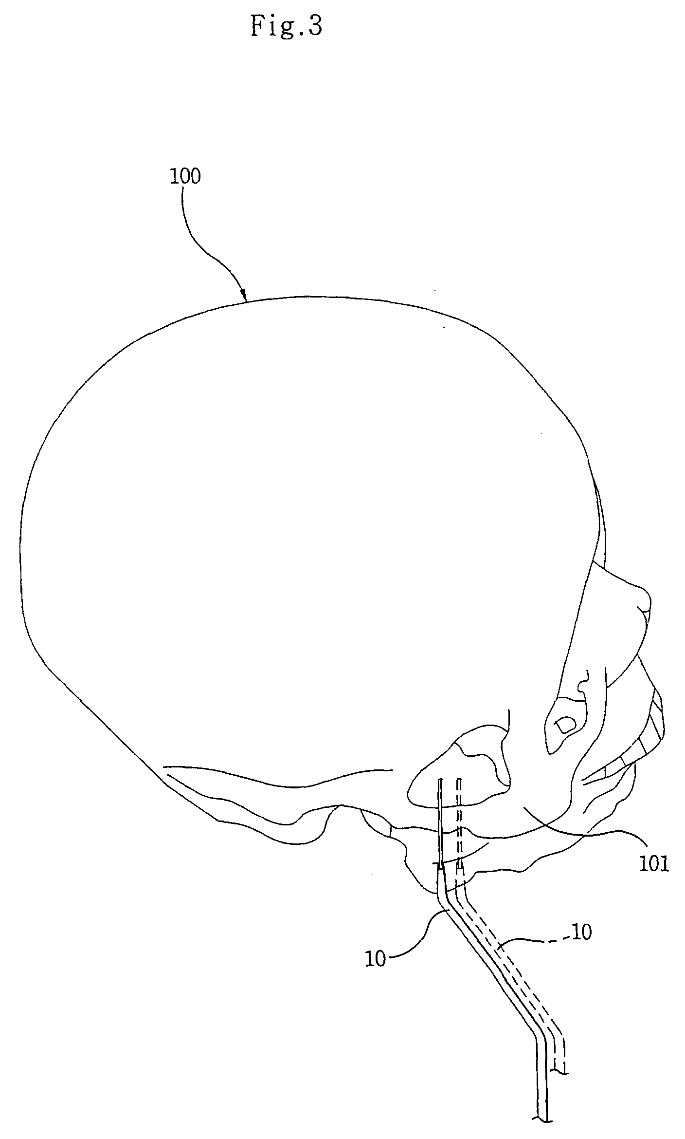
[0022]Hereinafter, the structure and operations of a surgical saw for cutting off cheek bones will be described in detail through preferred embodiments of the present invention.

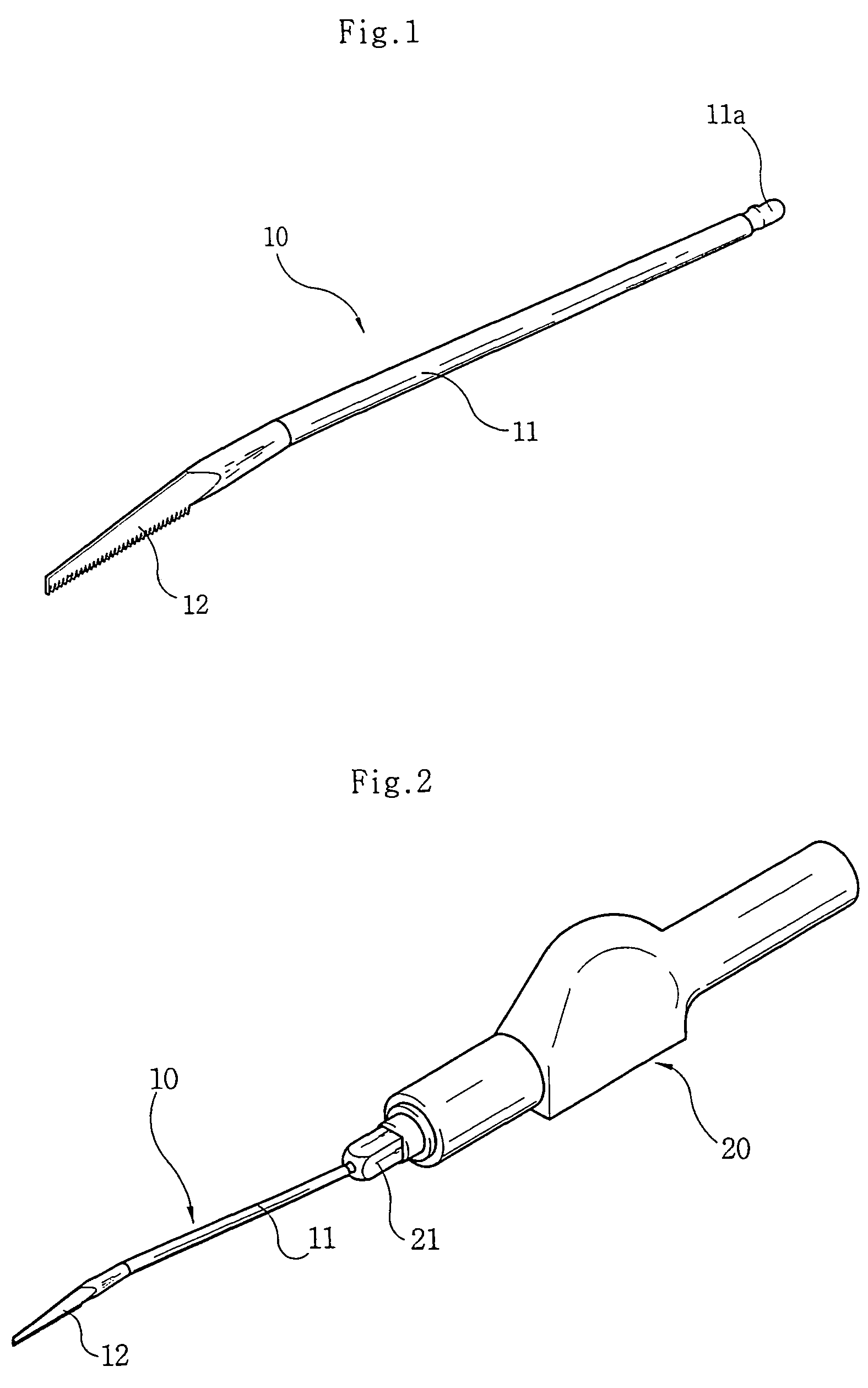
[0023]FIG. 4 is a perspective view for a surgical saw for cutting off cheek bones according to an embodiment of the present invention, and FIG. 5 is a perspective view for a motor-driven surgical saw to which a surgical saw for cutting off cheek bones is mounted according to an embodiment of the present invention.

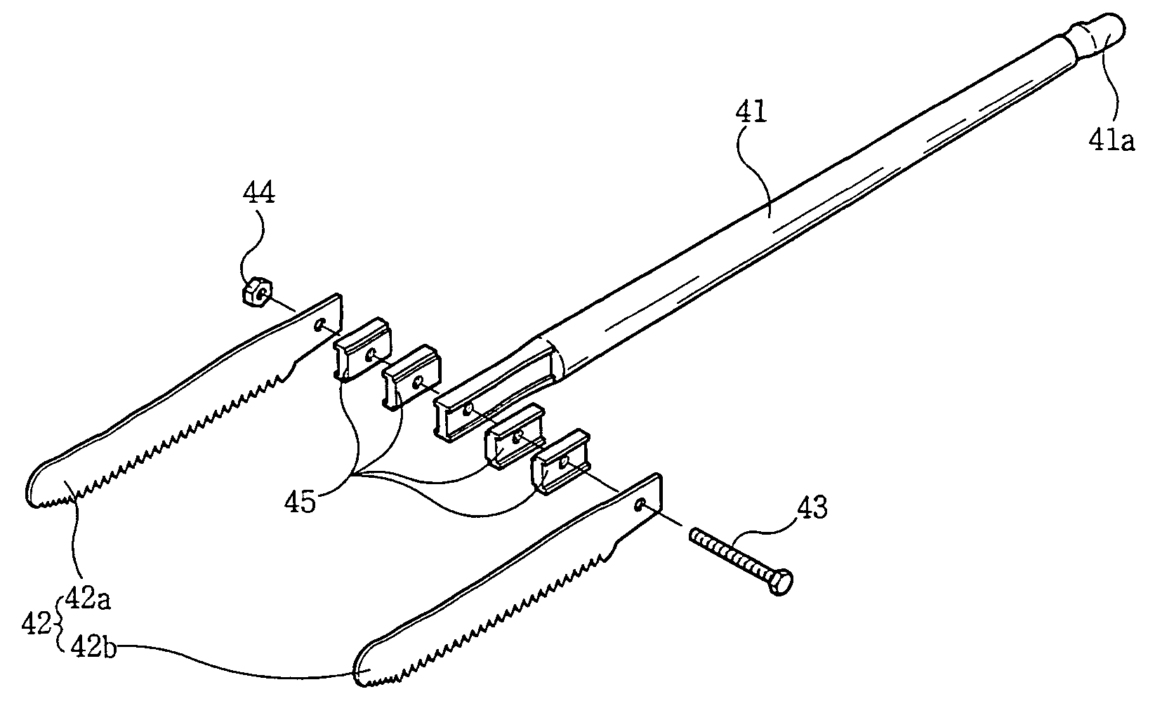
[0024]As shown in FIG. 4, a surgical saw 30 for cutting off cheek bones according to an embodiment of the present invention has an arm 31 of an elongate bar shape and a double saw blade part 32 mounted on the front end of the arm 31.

[0025]The arm 31 is a round bar of a certain length on the front end of which the double saw blade part 32 is mounted and on the rear end of which a fixture portion 31a having a connection structure is formed to be connected with a jaw 21 of a handle 20, as shown in FIG. ...


PUM


Abstract

The surgical saw according to the present invention comprises an arm fixed by mounting the rear end portion thereof in a jaw of a handle; and a double saw blade part connected with the front end portion of the arm and having two saw blades arranged side by side in a certain distance. In case that the surgical saw is used in surgeries for cutting off cheek bones, the surgical saw can precisely cut off portions of the cheek bones in a width set in advance by precisely cutting off two positions of the cheek bones in a precise cutting-off length at the same time so that the portions of cheek bones can be conveniently cut off, the periods of time for surgeries can be reduced, and an occurrence frequency of surgery aftereffects due to different cutting-off widths for the left and right cheek bones can be reduced.

Description

TECHNICAL FIELD[0001]The present invention relates to a surgical saw for cutting off cheek bones which is used for cutting off portions of cheek bones during plastic surgeries for smoothing bulged cheek bones, and more particularly to a surgical saw for cutting off cheek bones which has spacing-adjustable double saw blades capable of precisely cutting off cheek bones at one time in a predetermined width.BACKGROUND ART[0002]The cheek bones such as the zygomatic buttresses, are bones bulged out below the tails of the eyes on the both sides of a face. Appropriate cheek bone bulges give a vigorous and good look and a three-dimensional effect, but excessive cheek bone bulges cause a face to look wide and a nose to look relatively low in front view so that the bulges may be a factor for a face appearance to be deteriorated. Particularly, the excessive bulges together with a square chin which is distinctly protruded and angled cause a strong and rough appearance so that they give an advers...

Claims


Application Information

Patent Timeline
Patent Type & Authority Patents(United States)
IPC IPC(8): A61B17/56A61B17/14A61B17/16
CPCA61B17/14A61B17/148A61B17/144A61B17/16
Inventor LEE, JAE HWA
Owner LEE JAE HWA
Why Eureka
Try Eureka