Unlock instant, AI-driven research and patent intelligence for your innovation.

Repeat field detecting apparatus, video progressive conversion reproducing apparatus, repeat field detecting method, program, and recording medium

a repeat field and reproducing technology, applied in the field of repeat field detecting apparatus, video progressive conversion reproducing apparatus, repeat field detecting method, program, recording medium, etc., can solve the problems of false conversion, decrease increase in the number of discrepancy pixels, etc., and achieve the effect of improving image quality

Inactive Publication Date: 2008-01-29
PANASONIC CORP
View PDF19 Cites 4 Cited by
  • Summary
  • Abstract
  • Description
  • Claims
  • Application Information

AI Technical Summary

Benefits of technology

[0014]The probability of performing false progressive conversion is reduced, so as to improve the image quality of the output video image processed by video progressive conversion.
[0094]An effect is provided that when an irregular video input signal is obtained such that the material determination result varies continuously, continuous filter variation is suppressed, so that the image quality is improved. Further, the filter variation allowable limit and the depth d of filter change history can be changed, so that the sensitivity can be adjusted.

Problems solved by technology

Accordingly, false detection of a repeat field can cause false conversion such as the use of an inappropriate filter and the combining of video images that are intrinsically not to be combined to each other.
Accordingly, in a scene having little motion such as the case that motion occurs merely in a part of the image, the number of discrepancy pixels decreases, and hence a problem occurs that even a field which is intrinsically not a repeat field is determined as if a repeat field.
Further, when the video quality of video material generated by the 3-2-pulling down of motion picture material is degraded, that is, when noise is introduced into the video image, the difference in the video images due to the noise causes an increase in the number of discrepancy pixels.
This can cause a discrepancy in the images by the amount equal to the change in the images before and after the repeat field, and hence can increase the number of discrepancy pixels.
When this increase exceeds the threshold value for the repeat field detection, a problem occurs that even a repeat field is determined as if an ordinary field.
In such cases described here that the repeat field detection is not accurately achieved, the repeat field information inputted to the apparatus 326 cannot reflect appropriately the feature of the interlace video image inputted to the apparatus 301, so that the material determination can fail and that material determination and filter control can be difficult to be carried out accurately in the video progressive conversion.
This can cause frequent switching of filters and inappropriate selection of a filter.
These cause a problem of degradation in the quality of the output video image.
Nevertheless, in the first repeat field detecting means of the apparatus 357, in a scene having little motion, the number of discrepancy pixels becomes smaller than a predetermined threshold value even in a scene other than repeat fields, and hence repeat fields cannot be identified accurately.
Further, in case of degradation in the quality of the video material or in case of the use of three-dimensional noise reduction, video information does not completely agree even in a repeat field where the information should intrinsically agree with the former one.
This causes a problem that the number of discrepancy pixels exceeds the predetermined threshold value in the apparatus 357, and that accordingly repeat fields cannot be detected even in video material generated by the 3-2-pulling down of motion picture material.
In such cases described here that the repeat field detection is not accurately achieved, material determination and filter control become difficult to be carried out accurately in the video progressive conversion.
This can cause frequent switching of filters and inappropriate selection of a filter.
These cause a problem of degradation in the quality of the output video image.
That is, there is a problem that errors occur in the detection of repeat fields in case of a scene having little motion, in case of degradation in the quality of video material, in case that noise on the time axis is introduced owing to the use of three-dimensional noise reduction, or in case that the video is recorded in irregular patterns.

Method used


Image

  • Repeat field detecting apparatus, video progressive conversion reproducing apparatus, repeat field detecting method, program, and recording medium
  • Repeat field detecting apparatus, video progressive conversion reproducing apparatus, repeat field detecting method, program, and recording medium
  • Repeat field detecting apparatus, video progressive conversion reproducing apparatus, repeat field detecting method, program, and recording medium

Examples


embodiment 1

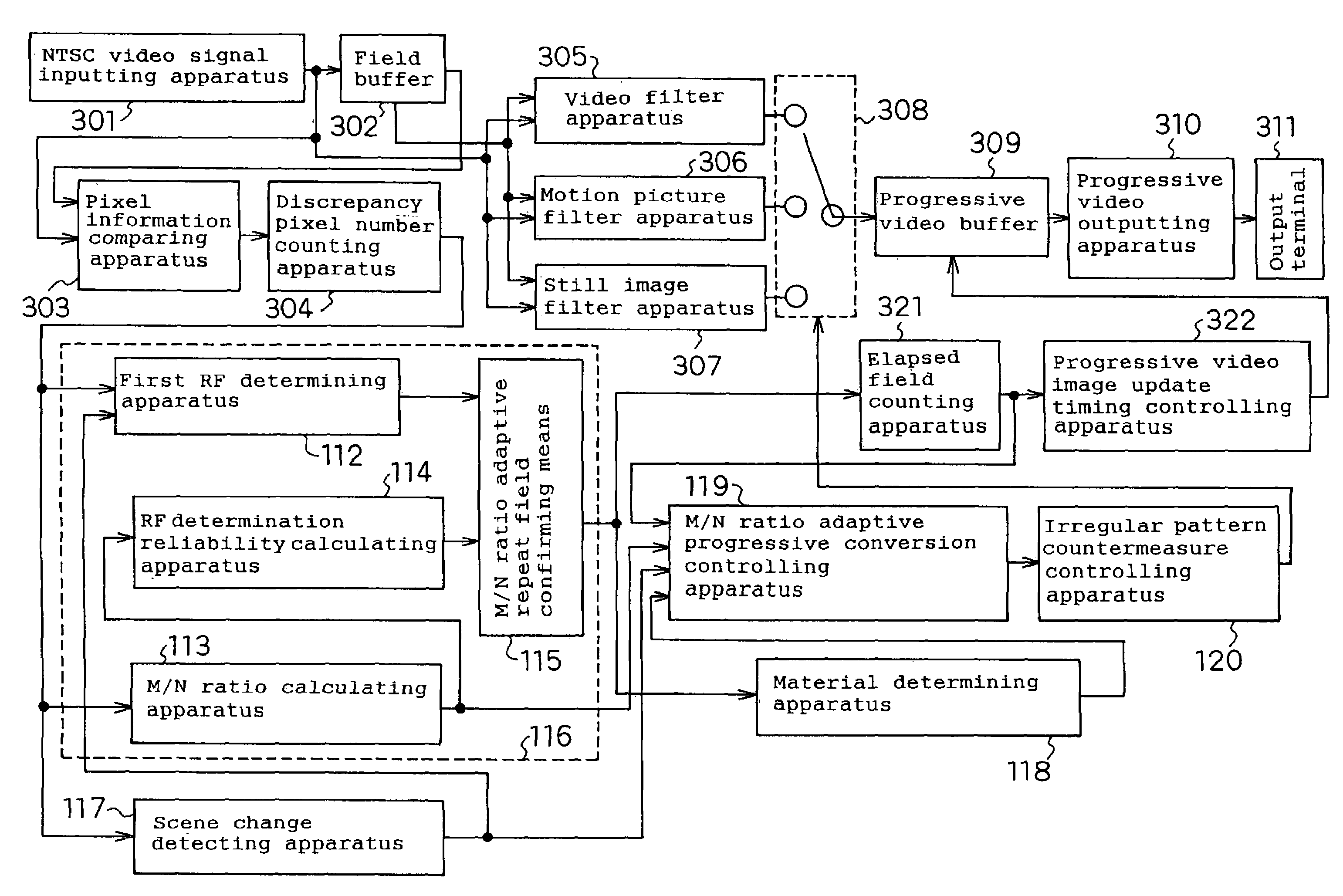
[0150]FIG. 1 is a block diagram showing a video progressive conversion reproducing apparatus according to Embodiment 1 of the invention. In FIG. 1, like components to FIG. 14 showing a block diagram of a prior art video progressive conversion reproducing apparatus are designated by like numerals. The subject matter different from FIG. 14 is described below.

[0151]Numeral 112 indicates a first RF determining apparatus of receiving the discrepancy pixel number counted in the apparatus 304, and then determining whether the present field is a repeat field or not. Numeral 113 indicates an M / N ratio calculating apparatus of receiving the discrepancy pixel number counted in the apparatus 304, and then calculating an M / N ratio indicating the characteristics of the motion and the noise on the time axis of the input video signal. Numeral 114 indicates an RF determination reliability calculating apparatus of receiving the M / N ratio calculated in the apparatus 113, and then outputting a value in...

embodiment 2

[0204]FIG. 7 is a block diagram showing a video progressive conversion reproducing apparatus according to Embodiment 2 of the invention. The differences of FIG. 7 from FIG. 1 are as follows. That is, the apparatus 247 is an M / N ratio adaptive composite RF determining means used in place of the RF determining apparatus 112. The apparatus 224 is a long term M / N ratio calculating apparatus used in place of the apparatus 113. The apparatus 225 is an M / N ratio adaptive scene change detecting apparatus used in place of the apparatus 117. FIG. 8 is a flow chart showing the contents of the process in the apparatus 224.

[0205]The apparatus 224 has apparatuses similar to the block of the first through fifth accumulated average calculating apparatuses in the apparatus 134 of FIG. 2. In Step 1410, on the basis of the output from the apparatus 225, the apparatus 224 determines whether the scene is a scene change or not. In case of a scene change, the procedure goes to Step 1411. Otherwise, the pr...


PUM


Abstract

Using an index indicating the amount of motion and noise in the video image calculated on the basis of the discrepancy pixel numbers of image two fields ago and the present image, the reliability of detection result is obtained and utilized, so as to improve the repeat field detection accuracy and the scene change detection accuracy. Further, adaptive filter accuracy is improved by changing the determination conditions in the determination of the filter to be used. In addition, filter control accuracy is improved by suppressing the filter fluctuation per unit time.

Description

[0001]This application is a U.S. National Phase Application of PCT International Application PCT / JP2003 / 014294.TECHNICAL FIELD[0002]The present invention relates to: a progressive conversion reproducing apparatus of converting an inputted interlace video signal into a progressive video signal; a repeat field detecting apparatus used in this progressive conversion reproducing apparatus so as to detect a repeat field; a repeat field detecting method; a program; and a recording medium.BACKGROUND ART[0003]FIG. 14 shows the configuration of a prior art progressive conversion reproducing apparatus. Numeral 301 indicates a video signal inputting apparatus of receiving an NTSC video signal from an external system and then converting the signal into digital data capable of being stored in a field buffer. Numeral 302 indicates a field buffer of accumulating two fields of the digital data converted by the apparatus 301. Numeral 303 indicates a pixel information comparing apparatus of comparing...

Claims


Application Information

Patent Timeline
Patent Type & Authority Patents(United States)
IPC IPC(8): H04N11/20H04N7/01
CPCH04N7/012
Inventor KURODA, KEIICHIITANI, TETSUYA
Owner PANASONIC CORP