Cross-track shielding in a GMR head

Inactive Publication Date: 2008-01-29
MAXTOR
View PDF20 Cites 20 Cited by
  • Summary
  • Abstract
  • Description
  • Claims
  • Application Information

AI Technical Summary

Problems solved by technology

Unfortunately, there is little to no discussion in Mao of how to manufacture such a structure.
Further, there is no discus

Method used


Image

  • Cross-track shielding in a GMR head
  • Cross-track shielding in a GMR head
  • Cross-track shielding in a GMR head

Examples


Embodiment Construction

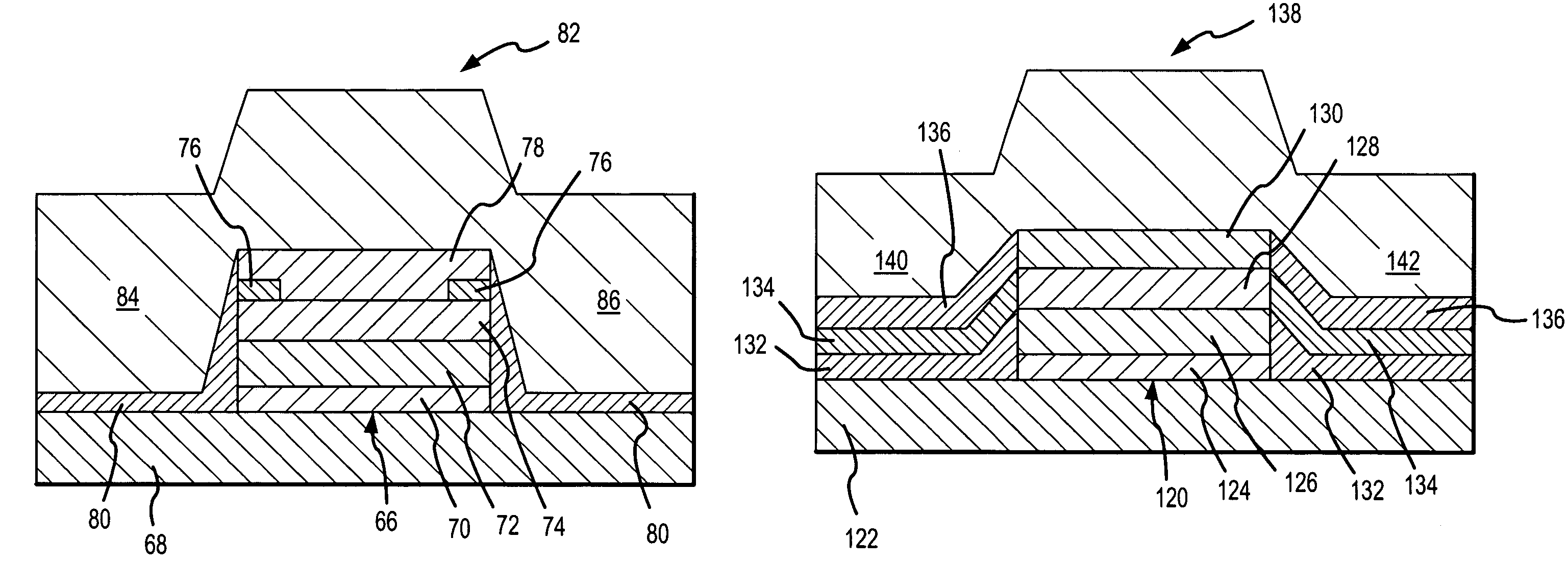
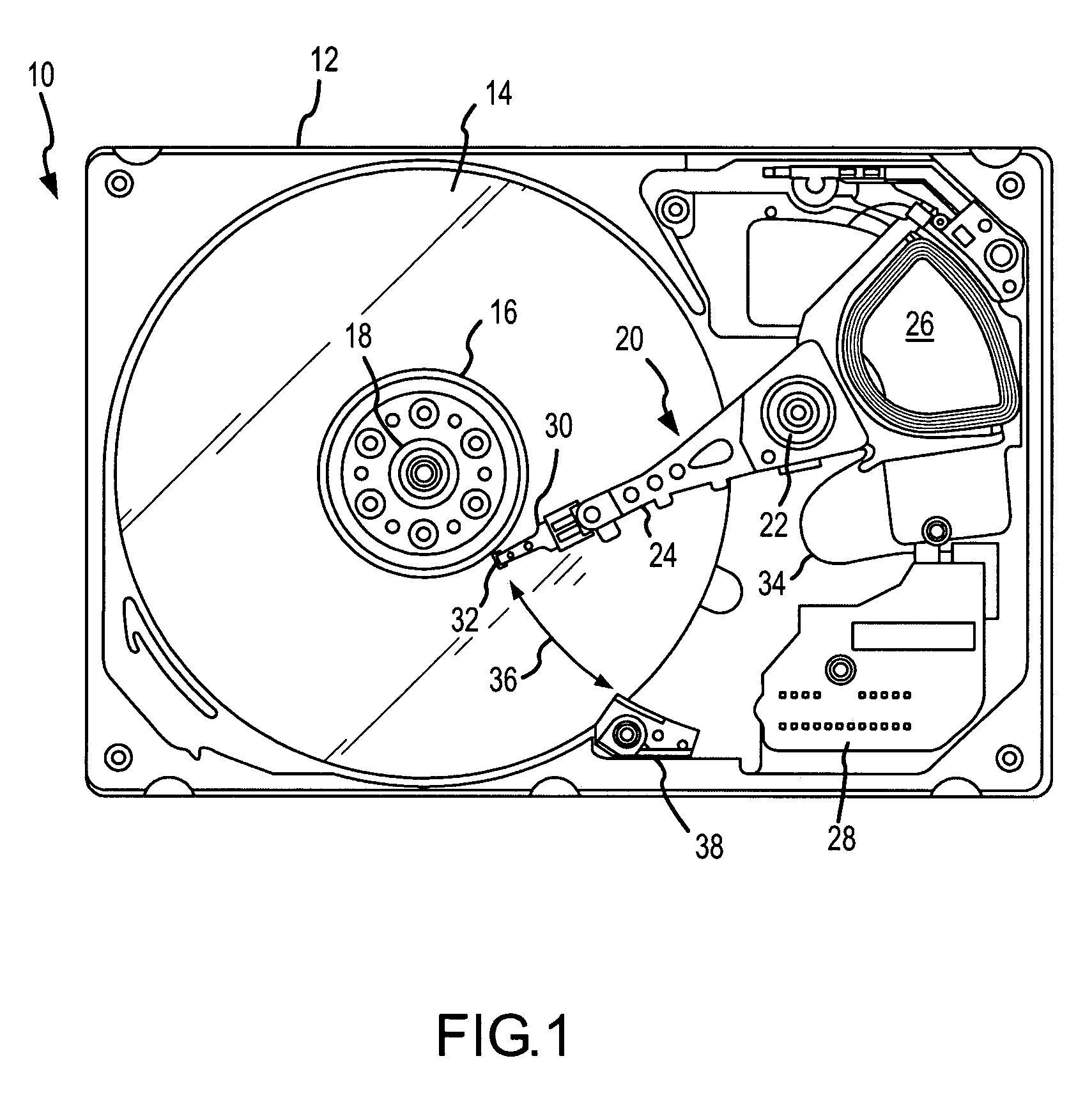
[0032]Reference will now be made to the accompanying drawings, which assist in illustrating the various pertinent features of the present invention. Although the present invention will now be described primarily in conjunction with disk drives, it should be expressly understood that the present invention might be applicable to other applications where side shielding of a magnetoresistive sensor is required / desired. In this regard, the following description of a GMR read element in a disk drive is presented for purposes of illustration and description. Furthermore, the description is not intended to limit the invention to the form disclosed herein. Consequently, variations and modifications commensurate with the following teachings, and skill and knowledge of the relevant art, are within the scope of the present invention. The embodiments described herein are further intended to explain best modes known of practicing the invention and to enable others skilled in the art to utilize th...


PUM


Abstract

A magnetoresistive read/write head includes an integral top and side shields deposited on top of and substantially surrounding the multiple layers of the MR sensor stack. Such a design is particularly advantageous in CPP designs in which the only spacing necessary between the side shields and the bottom shield is due to a gap layer. The integral top and side shields design works both with CPP heads having pile bias stabilization as well as those having permanent magnet abutted junctions or patterned exchange bias stabilization. In addition, the design is also advantageous in CIP heads having permanent magnet abutted junctions or patterned exchange bias stabilization. In this latter embodiment, it may be possible to reduce the profile of the permanent magnet and any conductors to increase the efficacy of the side shields.

Description

CROSS-REFERENCE TO RELATED APPLICATIONS[0001]This application claims priority from U.S. Provisional Patent Application No. 60 / 452,617, filed Mar. 6, 2003, entitled “Cross-Track Shielding to Reduce Magnetic to Physical Reader Width Offset”, the contents of which are incorporated herein by reference.FIELD OF THE INVENTION[0002]This application relates to a magnetoresistive (MR) read element arrangement for data storage applications, particularly a giant magnetoresistive (GMR) read element with cross-track shielding.BACKGROUND OF THE INVENTION[0003]In hard disk drives, data is written to and read from magnetic recording media, herein called disks, utilizing magnetoresistive (MR) transducers commonly referred to as MR heads. Typically, one or more disks having a thin film of magnetic material coated thereon are rotatably mounted on a spindle. An MR head mounted on an actuator arm is positioned in close proximity to the disk surface to write data to and read data from the disk surface.[0...

Claims


Application Information

Patent Timeline
IPC IPC(8): G11B5/39G11B5/10
CPCB82Y25/00G01R33/093G11B5/11G11B5/3163G11B5/39G11B5/3912G11B5/3932G11B5/398H01L43/08H10N50/10
Inventor WIESEN, KURTCROSS, WILLIAM R.
Owner MAXTOR
Why Eureka
Try Eureka