Rotary tool for spreading particulate materials and method of using the same
a technology of particulate materials and rotary tools, which is applied in the direction of hand cultivators, applications, ways, etc., can solve the problems of time-consuming and labor-intensive partspreading and leveling of particulate materials mounds, and the equally difficult distribution of particulate materials over the surfa
- Summary
- Abstract
- Description
- Claims
- Application Information
AI Technical Summary
Benefits of technology
Problems solved by technology
Method used
Image

Examples
first embodiment
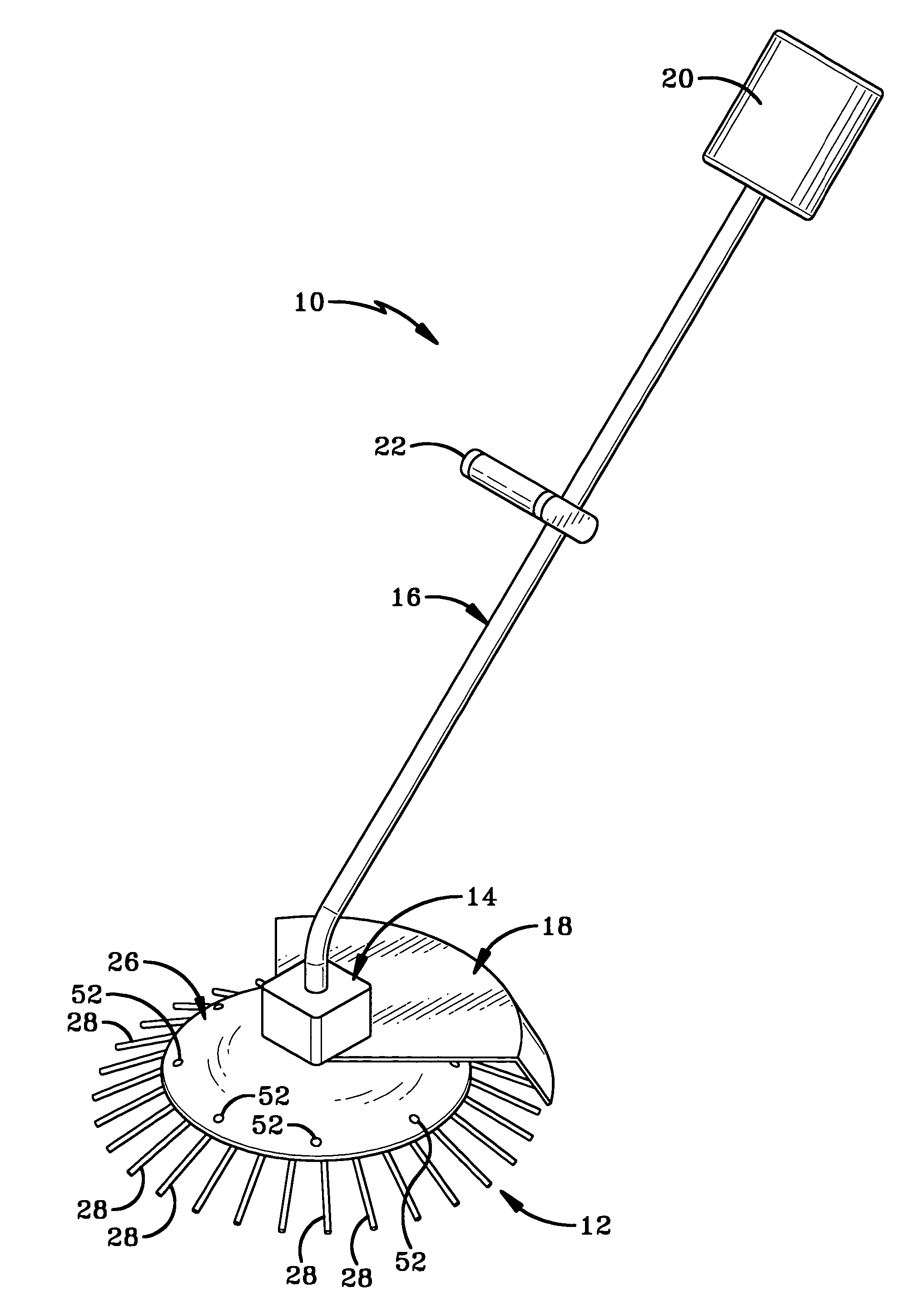
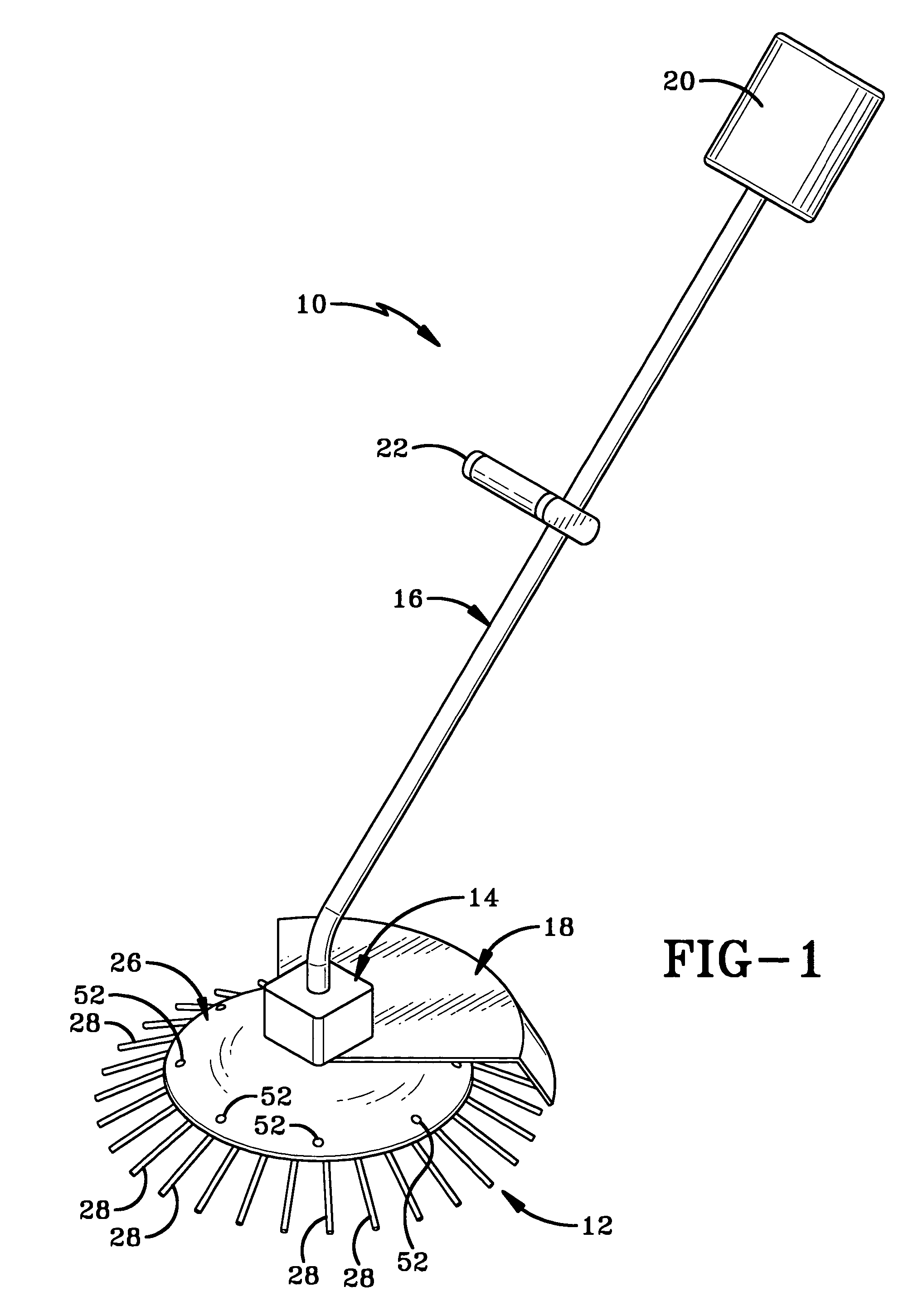
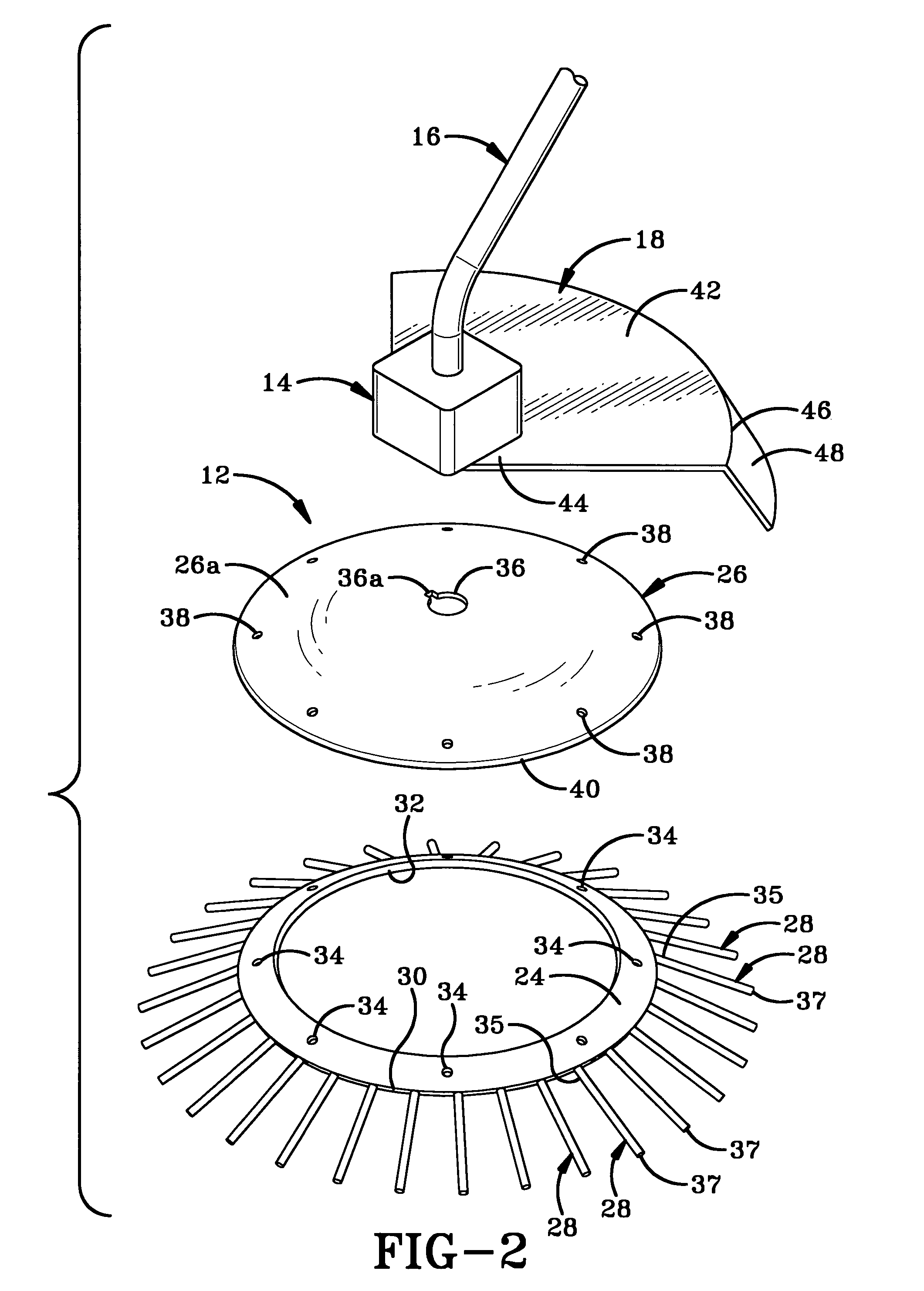
[0022]Referring to FIGS. 2-4, rotatable body 12 comprises a ring 24 and a plate 26 that are connected to stationary coupler 14. Ring 24 has a plurality of flexible fingers 28 radiating outwardly from its peripheral edge 30 and has a centrally located hole 32. Fingers 28 have first ends 35 and second ends 37. First ends 35 of fingers 28 are connected to ring 24 and second ends 37 are coplanar. The second ends 37 of fingers 28 preferably lie two to three inches outwardly from peripheral edge 30. Ring 24 preferably is manufactured from a plastic or rubber that is sufficiently rigid to move the particulate materials but is flexible enough that fingers 28 can bend slightly upon entering the particulate materials and spring back to their original position, thereby flicking particulate materials away from tool 10. A plurality of apertures 34 are provided at intervals around ring 24.
[0023]Plate 26 preferably is manufactured from a more rigid plastic or rubber than is ring 24 but is still pr...
second embodiment
[0028]Referring to FIG. 9, there is shown the rotatable body for use in association with tool 10, and generally indicated at 112. Rotatable body 112 comprises a rotatable body 170 having a convex cross-section and a centrally located aperture 136. Aperture 136 may include a slotted area 136a for correct alignment of a drive shaft (not shown) housed within stationary coupler 14 of tool 10. A plurality of fingers 128 radiate outwardly from the outer edge 172 of rotatable body 170. Rotatable body 170 preferably is manufactured from a rubber or plastic material that is strong enough to support a small amount of particulate materials thereon, but which allows fingers 128 to be flexible. Rotatable body 170 is connected to the drive shaft (not shown) extending outwardly from stationary coupler 14, through an aperture (not shown) in hood 18 and is secured thereto by a nut (not shown) as described with reference to rotatable body 12. Rotatable body 112 is used in the same manner described wi...
third embodiment
[0029]Referring to FIGS. 10-13, there is shown a rotatable body in accordance with the present invention and generally indicated at 212. Rotatable body 212 comprises a convexly domed rotatable body 270 having a central aperture 236 therein. Aperture 236 may be slotted as at 236a to receive a drive shaft (not shown) therethrough. A plurality of keyhole-shaped slots 274 are formed in rotatable body 270 proximate the outer edge 272 thereof. A plurality of fingers 228 are provided for insertion into slots 274. Each finger 228 has a bulbous head 278 and an elongated shaft 280. Head 278 of each finger 228 is received in the wider portion 274a of one of slots 274 and a section of shaft 280 is received in the narrow portion 274b of the same slot 274. When head 278 of a finger 228 is inserted into wider portion 274a of one of slots 274, it is pulled radially outwardly away from the center axis of rotatable body 270 as shown by arrow “E” (FIG. 13) and locks into a curved seat 282 formed in ou...
PUM
 Abstract
Description
Claims
Application Information
 - R&D
- Intellectual Property
- Life Sciences
- Materials
- Tech Scout
- Unparalleled Data Quality
- Higher Quality Content
- 60% Fewer Hallucinations
Browse by: Latest US Patents, China's latest patents, Technical Efficacy Thesaurus, Application Domain, Technology Topic, Popular Technical Reports.
© 2025 PatSnap. All rights reserved.Legal|Privacy policy|Modern Slavery Act Transparency Statement|Sitemap|About US| Contact US: help@patsnap.com