Foldable headrest assembly

a headrest and folding technology, applied in the field of headrests, can solve the problems of insufficient transportation for a modest sized family, inability to fold the headrest, and introduction of the same sedan, and achieve the effect of simple and efficient locking

Inactive Publication Date: 2008-02-05
WINDSOR MACHINE & STAMPING
View PDF51 Cites 77 Cited by
  • Summary
  • Abstract
  • Description
  • Claims
  • Application Information

AI Technical Summary

Benefits of technology

[0010]The foldable headrest assemblies of the present invention include a simple and efficient lock lever for maintaining the upright position of the foldable headrest assembly. The biasing members cooperate with each other to prevent the lock lever from unlocking and causing the plates to rotate from the upright position toward the forwardly folded position. The release mechanism is easy to use for moving the lock lever from the locked position to the unlocked position. Location of the ends of the conduit allow for various placements and uses of the foldable headrest assemblies.

Problems solved by technology

For example, a pickup truck is useful for transporting cargo, but it is inadequate transportation for a modest sized family.
Conversely, a mid-sized sedan provides sufficient seating for a typical family, but this same sedan falls short when the owner needs to transport a large object, such as furniture.
However, the headrest introduces a problem in multi-purpose vehicles with folding seats.
However, the headrest is an extension by design, adding to the volume occupied by a folded seat, and thereby subtracts from the available cargo space in a multi-purpose vehicle.
However, the procedure for removing and reattaching the seat is awkward and complicated and removal can be impractical when there is no convenient place to store the seat.
However, a detached headrest poses additional problems with storage of the headrest when the seat is in a folded or storage position and additionally the headrest may be lost or damaged during the removal.
However, the previous folding headrests included rather complicated locking mechanisms for securing the headrest into a position.

Method used


Image

  • Foldable headrest assembly
  • Foldable headrest assembly
  • Foldable headrest assembly

Examples


first embodiment

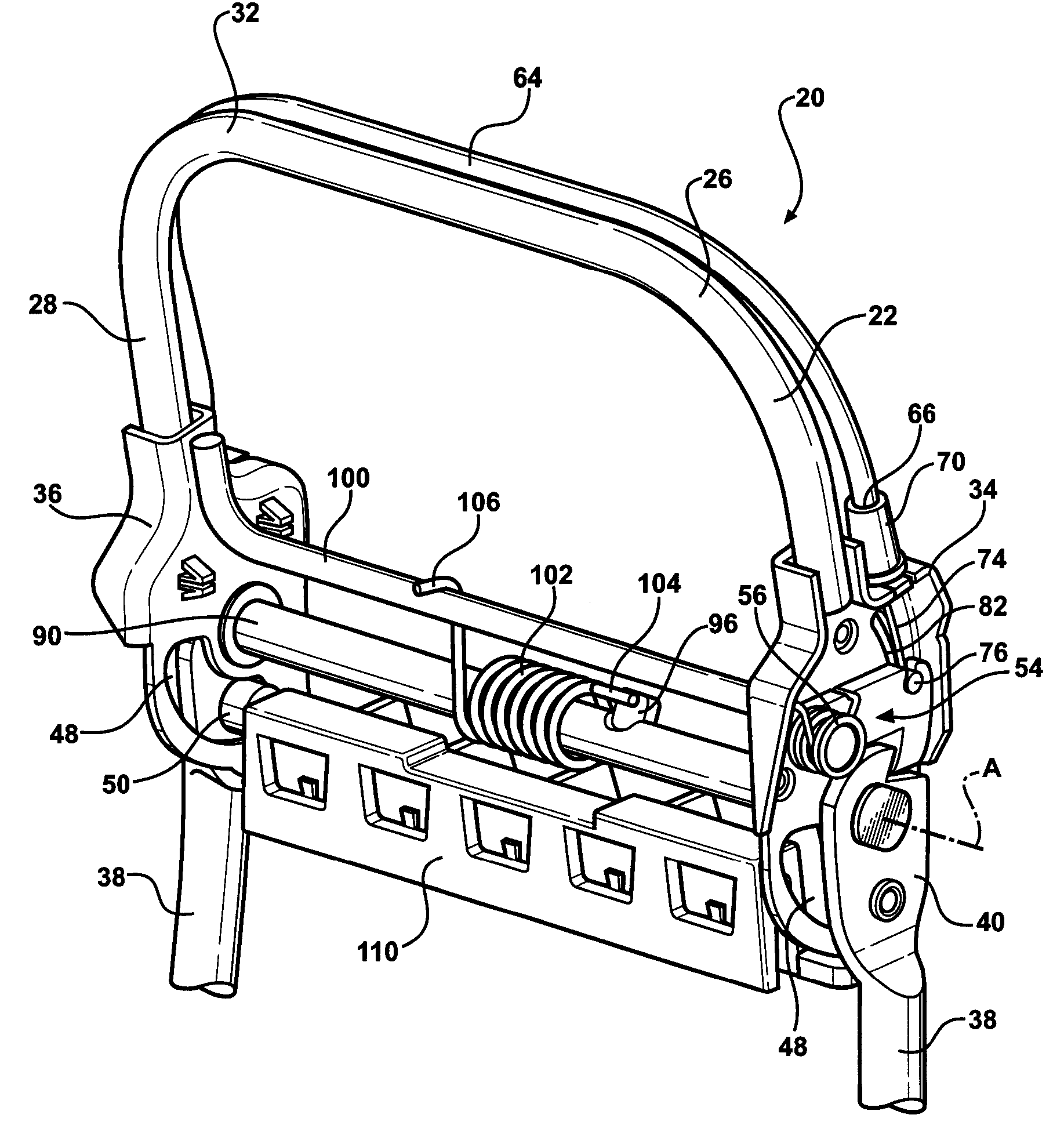
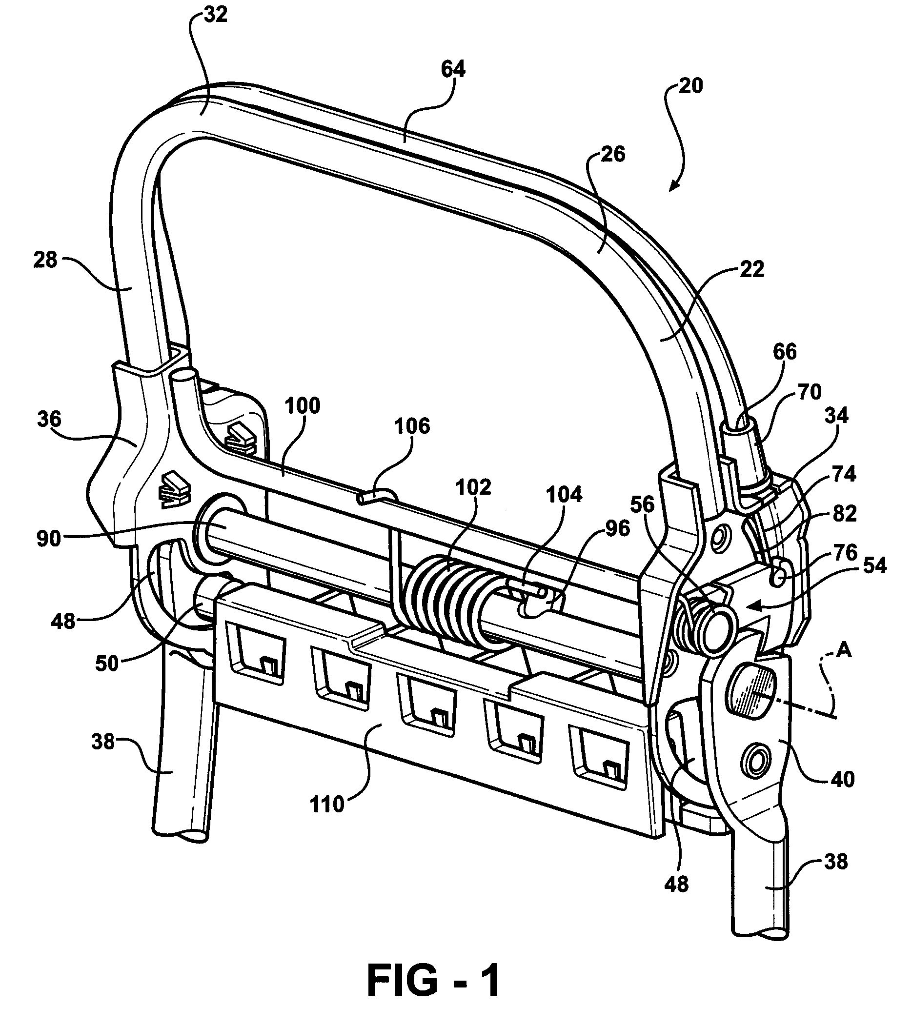
[0034]Focusing on FIG. 7, the latch lever 52 in the first embodiment is generally L-shaped and rotatably supported on the first plate 34. The latch lever 52 defines a C-shaped pocket 58 at a distance from the support and rotation point of the latch lever 52. The latch lever 52 engages into a notch 60 on the first paddle 40 in the latched position when the headrest assembly 20 is in the upright position. The latch lever 52 in the unlatched position disengages the notch 60 allowing the first and second plates 34, 36 to rotate about the axis (A) toward the forwardly folded position.

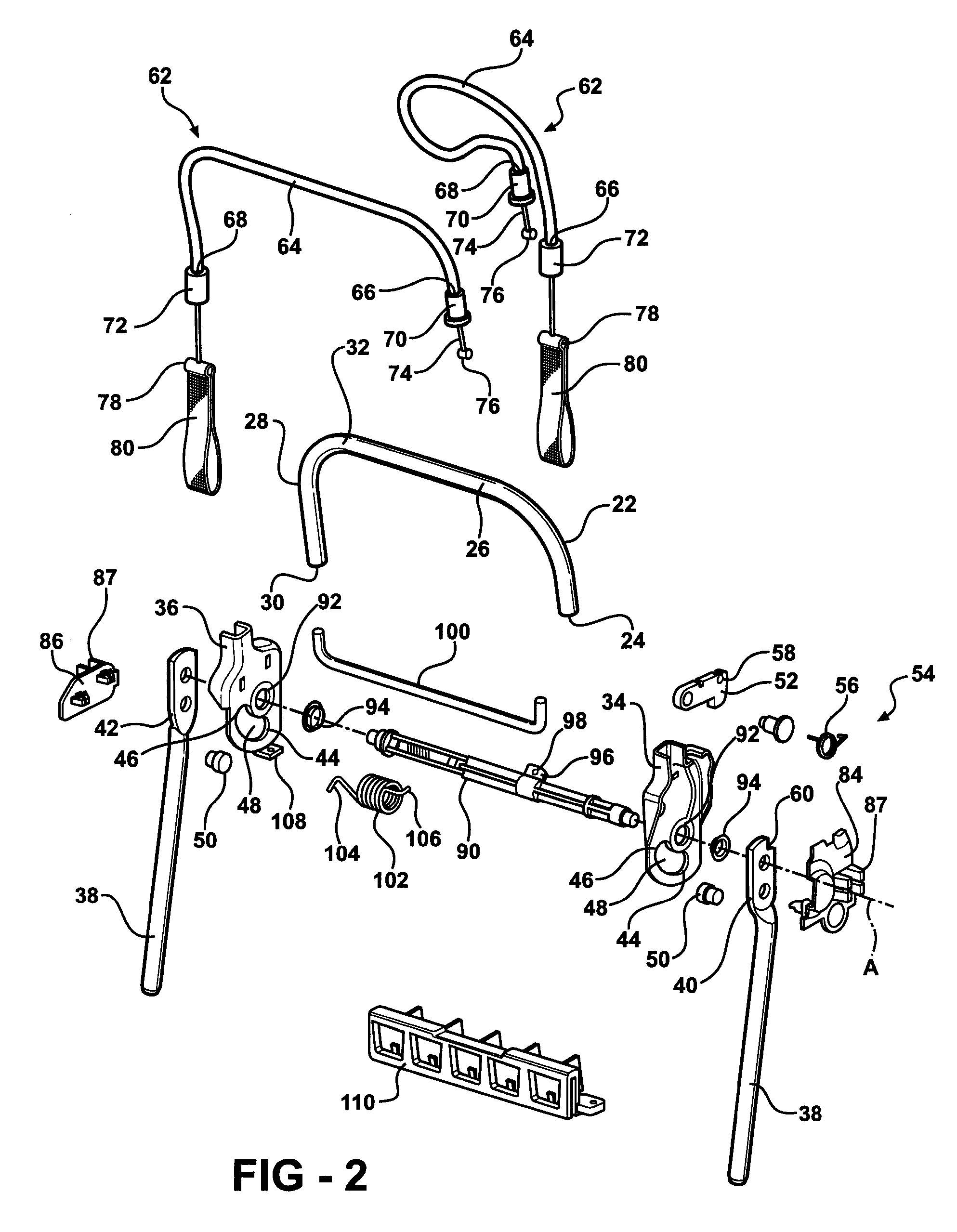
[0035]In the first embodiment as seen in FIGS. 2, 7 and 8, the release mechanism 54 further includes a motion transmitting cable 62 with a sheath 64 having a first end 66 and a second end 68. The first end 66 includes a first fitting 70 and the second end 68 includes a second fitting 72. A core 74 is movably disposed within the sheath 64 for transmitting the manual force that rotates the latch lever 52 out o...

second embodiment

[0041]Focusing on FIG. 9, the latch lever 52 in the second embodiment presents a face 116 that engages the second stop 46 of the first plate 34 in the latched position when the headrest assembly 20 is in the upright position. The latch lever 52 in the unlatched position disengages the second stop 46 allowing the first and second plates 34, 36 to rotate about the axis (A) toward the forwardly folded position.

[0042]The release mechanism 54 of the second embodiment, as shown in FIGS. 3, 4, and 9, is a design typically used in the last row of a multi-purpose vehicle, i.e., the third row of a minivan. The seat frame 38 presents a flange 118 extending upward from the seat frame 38 spaced from and parallel to the first paddle 40. The release mechanism 54 includes a latch handle 120 that extends between and is rotatably supported by the first paddle 40 and the flange 118. The latch handle 120 defines a U-shaped bow and the latch lever 52 is supported on the latch handle 120. A pull strap 12...

third embodiment

[0044]Referring to FIGS. 10-16, the foldable headrest assembly 200 is shown and will now be discussed in further detail below.

[0045]A vehicle including seats 204 is shown generally at 202 (in phantom) FIGS. 10 and 11. The seats 204 include a base 206 and a back 208 extending from the base 206. The foldable headrest assemblies 200 are operatively connected to the seats 204 by a first paddle 210 and a second paddle 212. For example, the paddles 210, 212 of the foldable headrest assemblies 200 are slidably disposed into a top portion 214 of the back 208 of the seats 130. In FIG. 10, the foldable headrest assemblies 200 and the backs 208 of the seats 204 are shown in an upright position. Referring to FIG. 11, the foldable headrest assemblies 200 and the backs 208 of the seats 204 are shown in a forwardly folded position, except at a driver location (D). It is to be appreciated by those of ordinary skill in the art that the present invention is not limited to any particular seat and / or v...


PUM


Abstract

The foldable headrest assembly includes a first and second support and a first and second paddle. A first and second plate extending from the supports and supported by the paddles rotate in unison about a first axis (A1) from an upright to a forwardly folded position. A lock lever rotatably supported by the first plate rotates about a second axis (A2) between a locked position and an unlocked position. A first biasing member (FBM) is disposed between the plates and a second biasing member (SBM) is supported by the first plate engaging the lock lever. The FBM rotatably biases the supports about the A1 toward the forwardly folded position and the SBM rotatably biases the lock lever about the A2 toward the locked position in a common rotational direction as the rotation of the supports about the A1. A release mechanism for rotating the lock lever is also disclosed.

Description

CROSS REFERENCE TO RELATED APPLICATION[0001]This application claims the benefit of U.S. Provisional Patent Application Ser. No. 60 / 731,317 filed on Oct. 28, 2005, which is hereby incorporated by reference, and is a continuation-in-part of U.S. patent application Ser. No. 11 / 106,818 filed on Apr. 15, 2005, which claimed priority to U.S. Provisional Patent Application Ser. No. 60 / 562,662 filed on Apr. 15, 2004.BACKGROUND OF THE INVENTION[0002]1. Field of the Invention[0003]The subject invention relates to headrests for vehicle seats, and more particularly, to a folding headrest assembly that allows for compact storage of vehicle seats.[0004]2. Description of the Prior Art[0005]By way of background, automobile consumers are increasingly demanding multi-purpose vehicles that can be modified to transport either people or cargo. For example, a pickup truck is useful for transporting cargo, but it is inadequate transportation for a modest sized family. Conversely, a mid-sized sedan provide...

Claims


Application Information

Patent Timeline
Patent Type & Authority Patents(United States)
IPC IPC(8): A47C1/10
CPCB60N2/4844B60N2/4855B60N2/856B60N2/844
Inventor BROCKMAN, MARK ANTHONYBARKO, JERRY SCOTTKAYAHARA, EVAN MURRAY
Owner WINDSOR MACHINE & STAMPING
Why Eureka
Try Eureka