Direct backlight module

a backlight module and direct technology, applied in shaving accessories, lighting and heating equipment, instruments, etc., can solve the problems of unfavorable uniform brightness of the overall backlight module, complicated design and manufacturing procedures, and inability to control the brightness uniformity

Active Publication Date: 2008-02-05
AU OPTRONICS CORP
View PDF5 Cites 4 Cited by
  • Summary
  • Abstract
  • Description
  • Claims
  • Application Information

AI Technical Summary

Benefits of technology

[0012]The primary objective of this invention is to provide a direct backlight module. By disposing a reflector on the corner portions of the backlight module, the undesired dark areas on the corner portions or the edges of the backlight module can be reduced.
[0013]Another objective of this invention is to provide an LCD comprising a direct backlight module. By disposing a reflector on the corner portions of the backlight module, the brightness of the backlight module can be more uniform, resulting in the enhancement of the overall quality of the LCD.

Problems solved by technology

Nevertheless, there is no light source disposed on the corner or edge portions of the backlight module because the undesired dark areas may occur in those parts, thereby causing the brightness of the overall backlight module to not be uniform.
Additional light sources that are disposed on the corner or edge portions of the backlight module make the design and manufacturing procedures more complicated.
Thus, it is not facilitated to control the uniformity of the brightness by adding light sources at the edges and corners.

Method used


Image

  • Direct backlight module
  • Direct backlight module
  • Direct backlight module

Examples


Embodiment Construction

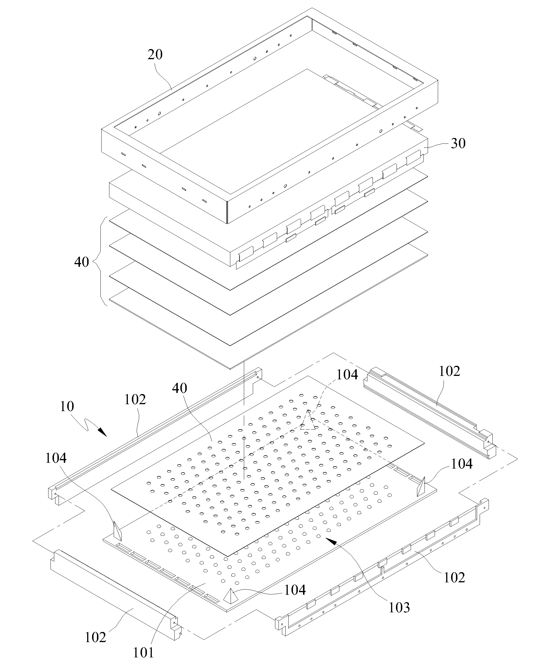
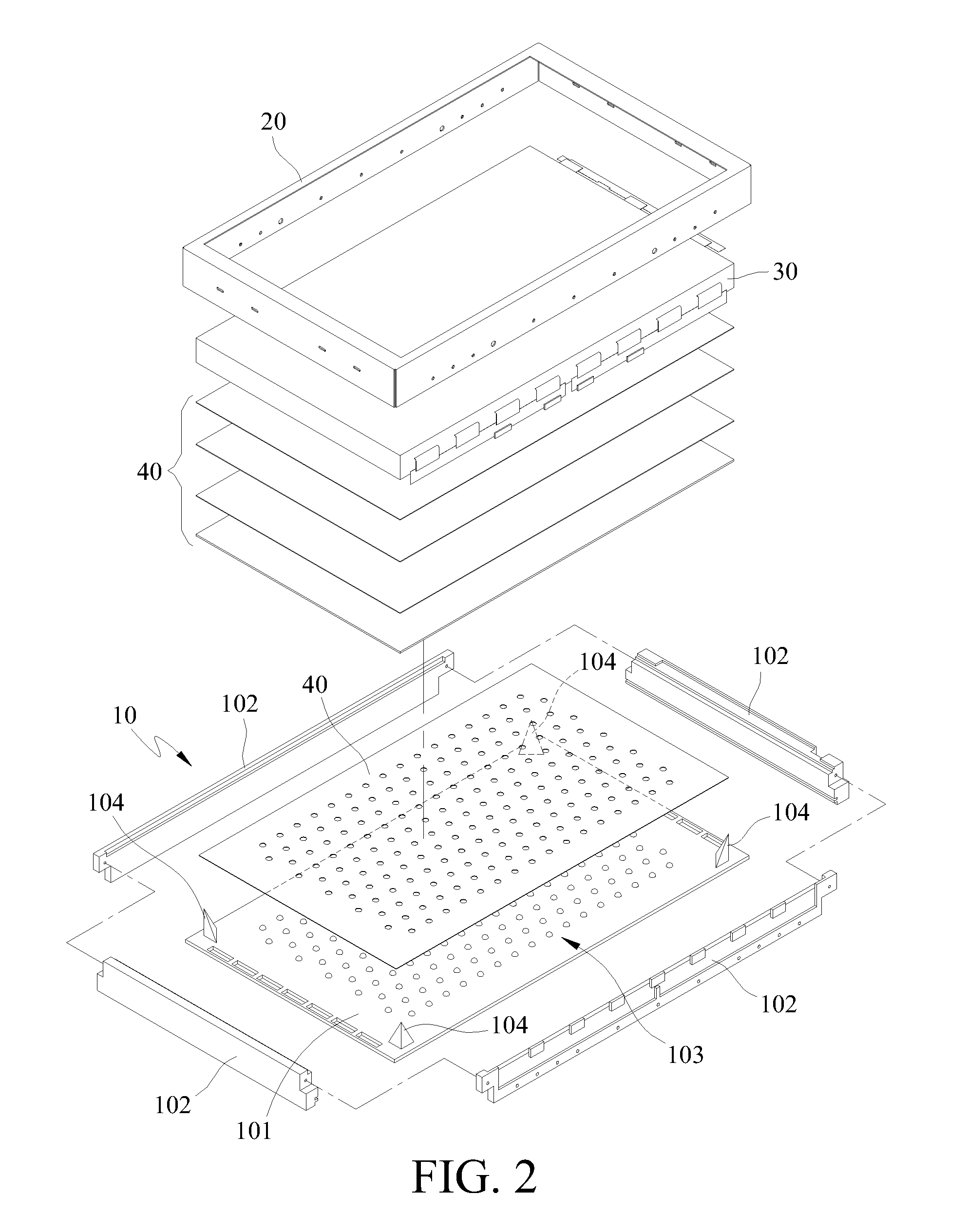
[0027]FIG. 2 is a perspective view of the LCD according to the present invention. The LCD comprises an LCD panel 30, a front bezel 20 disposed above the LCD panel 30, and a backlight module 10 that has at least one light source. Preferably, at least one light source should be an LED array 103 disposed on the back bezel 101. A frame 102 is disposed along the two adjacent edge portions of the back bezel 101. The frame 102 and the back bezel 101 form at least one corner portion. There are a plurality of optical films 40 disposed between the LCD panel 30 and the backlight module 10 for enhancing the efficiency of light usage and luminance promotion. The optical films 40 can be diffusing films, prism films, acrylic films and / or light enhancing films.

[0028]There are reflectors 104 disposed on the corner portions of the back bezel 101. The reflectors 104 are provided for reducing dark areas occurring on the corners or edges of the backlight module and for increasing the uniformity of the l...


PUM


Abstract

A plurality of reflecting structures are provided at the corner portions of a backlight module, so that the dark areas occurring at the corner portions or edges of the backlight module are prevented from forming, thereby uniforming the luminance performed by the display.

Description

CROSS-REFERENCES TO RELATED APPLICATIONS[0001]This application is a continuation-in-part of U.S. Ser. No. 11 / 278,619, filed on Apr. 4, 2006, which claims the priority of Taiwan Patent Application No. 094143406.[0002]This application claims the benefit from the priority of Taiwan Patent Application No. 095145678 filed on Dec. 7, 2006, the disclosures of which are incorporated by reference herein in their entirety.BACKGROUND OF THE INVENTION[0003]1. Field of the Invention[0004]The present invention relates to a backlight module, especially to a direct backlight module and a liquid crystal display (LCD) using the same, whereby the undesired dark areas on the corners and / or edges of the display can be efficiently reduced, resulting in a uniform overall luminance.[0005]2. Descriptions of the Related Art[0006]Liquid crystal displays (LCDs) have become the most popular displays because of the light weight and good displaying quality. The backlight module is an important illumination struct...

Claims


Application Information

Patent Timeline
Patent Type & Authority Patents(United States)
IPC IPC(8): F21V15/00
CPCG02F1/133605G02F1/133603
Inventor HSIAO, MENG-JIACHOU, SHEN-HONG
Owner AU OPTRONICS CORP
Why Eureka
Try Eureka