Exterior aircraft light

a technology for aircraft and light sources, applied in vehicle lighting systems, lighting and heating apparatuses, transportation and packaging, etc., can solve the problems of inability to accurately assess the unprojected longitudinal extension of elongated led light sources, unsatisfactory artefacts in the output light intensity distribution, and inability to achieve the effect of reducing the cost of production and maintenan

Active Publication Date: 2017-10-03
GOODRICH LIGHTING SYST GMBH
View PDF9 Cites 2 Cited by
  • Summary
  • Abstract
  • Description
  • Claims
  • Application Information

AI Technical Summary

Benefits of technology

[0007]The angled orientation directions of the first and second lighting units allow for a reduction of undesired artefacts in the overall output light intensity distribution of the exterior aircraft light. In particular, artefacts in the output light intensity distribution of the first lighting unit are smoothened by the output light intensity distribution of the second lighting unit, and vice versa. In other words, non-avoidable artefacts of the individual lighting units due to the extended nature of the respective LED light sources do not add up, as they would for identical or parallel orientation directions of the elongated LED light sources, but at least partially cancel each other out due to the angled orientation directions of the elongated LED light sources. The artefacts of the individual lighting units arise from the fact that the collimating optical systems cannot perfectly collimate the light emitted by an extended light source. Even if the collimating optical systems were a perfectly collimating optical systems, which is not required by the exterior aircraft light according to the invention, they could only perfectly collimate light emitted by a point light source. However, with the LED light source having a longitudinal extension as well as a transverse extension, i.e. with the LED light source having an extended light emitting surface, the collimating action of the collimating optical systems is inherently imperfect. With such elongated LED light sources generally having surface points of higher light emission and surface points of lower light emission, the output light emission distribution of an individual lighting unit also has areas of higher light intensity and areas of lower light intensity. As said surface points of stronger light emission and surface points of lower light emission are often inherently contained in a particular type of elongated LED light source, such as a line arrangement of various LEDs, identical or parallel orientation directions of the elongated LED light sources across the plurality of lighting units could lead to the areas of lower emission superimposing and leading to comparably dark spots in the overall output light intensity distribution of the exterior aircraft light. The angled arrangement of the first and second lighting units prevents such superimposition and prevents or reduces areas in the output light intensity distribution of the exterior aircraft light that are perceived as dark spots.
[0023]According to a further embodiment, an output light intensity distribution of the exterior aircraft light is a rotationally symmetric light intensity distribution. Such a rotationally symmetric light intensity distribution allows for a particularly uniform illumination arround a target direction. This is particularly desirable in the field of aircraft head lights, such as aircraft landing lights.

Problems solved by technology

Such exterior aircraft lights, having a plurality of lighting units, often have undesired artefacts in their output light intensity distribution.
The artefacts of the individual lighting units arise from the fact that the collimating optical systems cannot perfectly collimate the light emitted by an extended light source.
However, with the LED light source having a longitudinal extension as well as a transverse extension, i.e. with the LED light source having an extended light emitting surface, the collimating action of the collimating optical systems is inherently imperfect.
As the elongated LED light sources may be arranged at different heights with respect to the base plate and / or may be inclined with respect to the base plate, looking at the unprojected longitudinal extensions of the elongated LED light sources would not always allow for this assessment.
However, due to practical optical systems commonly not being perfectly collimating and due to the extended nature of the LED light source, the collimating optical system does not provide for a perfect collimation, with all light emitted by the elongated light source being bundled in the main output direction.
While they have an extended light emitting surface, all of the plurality of LEDs can be arranged very close to the focal point of the optical system, leading to a high degree of collimation despite the extended light emitting surface.

Method used


Image

  • Exterior aircraft light
  • Exterior aircraft light
  • Exterior aircraft light

Examples


Embodiment Construction

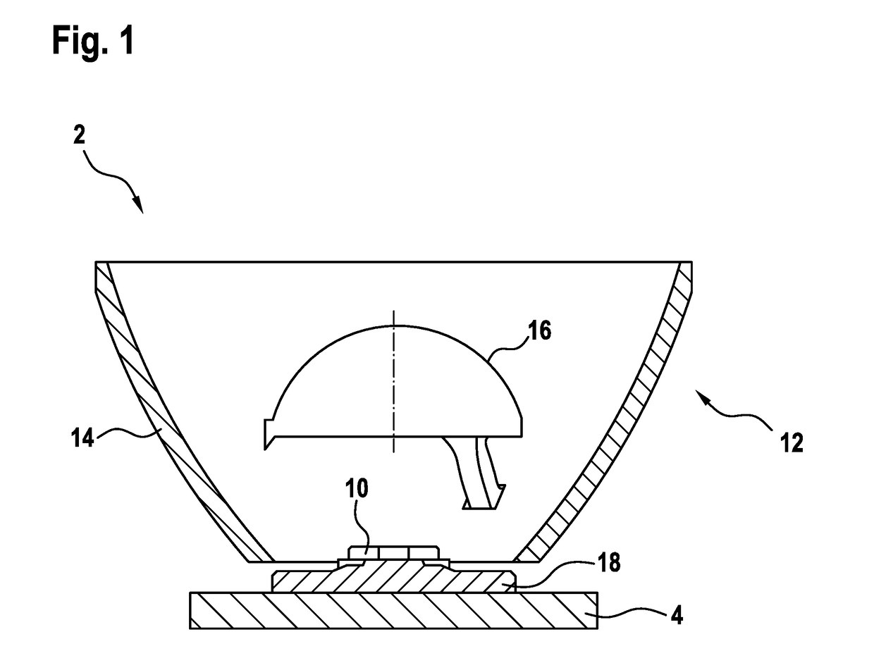
[0036]FIG. 1 shows an exemplary lighting unit 2, arranged on an exemplary base plate 4, wherein the exemplary lighting unit 2 can be used in exterior aircraft lights in accordance with exemplary embodiments of the invention.

[0037]The lighting unit 2 has a mounting structure 18, onto which an elongated LED light source 10 is mounted. The lighting unit 2 further comprises a collimating optical system 12, which is also mounted to the mounting structure 18. The mounting structure 18 provides for the attachment between the elongated LED light source 10 and the collimating optical system 12 and the base plate 4. In this way, the mounting structure 18 fixes the geometric relationship of these components to each other. It is pointed out that it is also possible that the elongated LED light source 10 and the collimating optical system 12 are directly mounted to the base plate 4.

[0038]The collimating optical system 12 comprises a parabolic reflector 14 and a collimating lens 16. The collimati...


PUM


Abstract

An exterior aircraft light includes a base plate and a plurality of lighting units arranged on the base plate, wherein each of the plurality of lighting units includes an elongated LED light source for emitting light, the elongated LED light source having a light emitting surface with a longitudinal extension and a transverse extension, with the longitudinal extension being greater than the transverse extension and with a projection of the longitudinal extension onto the base plate defining an orientation direction of the elongated LED light source, and a collimating optical system for collimating the light emitted by the elongated LED light source towards a main output direction, wherein the plurality of lighting units has at least a first lighting unit and a second lighting unit.

Description

FOREIGN PRIORITY[0001]This application claims priority to European Patent Application No. 15 150 020.4 filed Jan. 2, 2015, the entire contents of which is incorporated herein by reference.TECHNICAL FIELD[0002]The present invention relates to exterior aircraft lighting. In particular, it relates to an exterior aircraft light that has a plurality of similar lighting units, such as for example employed as aircraft headlights.BACKGROUND OF THE INVENTION[0003]Almost all aircraft have exterior lighting. Exterior lighting serves a plurality of purposes. While some exterior aircraft lights provide active visibility, i.e. they allow for the pilots and the crew to examine the aircraft environment, other exterior aircraft lights provide for passive visibility, i.e. they make the aircraft visible to others, particularly in the dark. Yet other exterior aircraft lights are provided for illuminating certain parts of the aircraft, such as engine scan lights, or provide for an illumination of the im...

Claims


Application Information

Patent Timeline
Patent Type & Authority Patents(United States)
IPC IPC(8): B64D47/02F21V5/04F21S8/10B64D47/04F21V7/06F21W107/30F21Y115/10
CPCF21V5/048B64D47/02B64D47/04F21S48/1154F21V7/06B64D2203/00F21W2101/06F21Y2115/10F21S41/143F21W2107/30F21S41/30F21S41/25F21S41/141F21W2102/00F21S41/151F21S41/153
Inventor JHA, ANIL KUMARHESSLING-VON HEIMENDAHL, ANDRE
Owner GOODRICH LIGHTING SYST GMBH
Why Eureka
Try Eureka