Surface roughness/contour shape measuring apparatus

a measuring apparatus and surface roughness technology, applied in the direction of measuring devices, mechanical roughness/irregularity measurements, instruments, etc., can solve the problems of limiting the range of workpieces that can be measured by the surface roughness/contour shape measuring apparatus, inability to measure a workpiece, and unwanted effect on measuring accuracy

Inactive Publication Date: 2008-02-12
TOKYO SEIMITSU
View PDF21 Cites 12 Cited by
  • Summary
  • Abstract
  • Description
  • Claims
  • Application Information

AI Technical Summary

Benefits of technology

[0014]That is, when the Y-axis workpiece driving unit is used as described above, as there is a limit to its weight-handling capacity, it is not possible to measure a workpiece whose weight exceeds the weight-handling capacity, thus limiting the range of workpiece that can be measured by the surface roughness / contour shape measuring apparatus.
[0018]In view of the above problems, it is an object of the present invention to provide a surface roughness / contour shape measuring apparatus that can move the probe relative to the workpiece within the orthogonal X-Y plane by employing a relatively inexpensive construction.
[0019]It is another object of the present invention to provide a surface roughness / contour shape measuring apparatus that can measure the surface shape of the workpiece within the orthogonal X-Z plane or along a sloping surface by employing a relatively inexpensive construction.

Problems solved by technology

However, the prior art surface roughness / contour shape measuring apparatus, in which the movement of the pickup 6 relative to the workpiece along one direction (Y direction) on the measurement surface is accomplished by employing a driving unit for driving the workpiece, has had the following problems.
That is, when the Y-axis workpiece driving unit is used as described above, as there is a limit to its weight-handling capacity, it is not possible to measure a workpiece whose weight exceeds the weight-handling capacity, thus limiting the range of workpiece that can be measured by the surface roughness / contour shape measuring apparatus.
Another problem has been that, a the center of mass affects the distortion of the moving table and the driving of the unit, the amount of deflection changes depending on the center of mass and the mounting position of the workpiece, thus causing an unwanted effect on the measuring accuracy.

Method used


Image

  • Surface roughness/contour shape measuring apparatus
  • Surface roughness/contour shape measuring apparatus
  • Surface roughness/contour shape measuring apparatus

Examples


Embodiment Construction

[0029]Preferred embodiments of the present invention will be described in detail below while referring to the attached drawings.

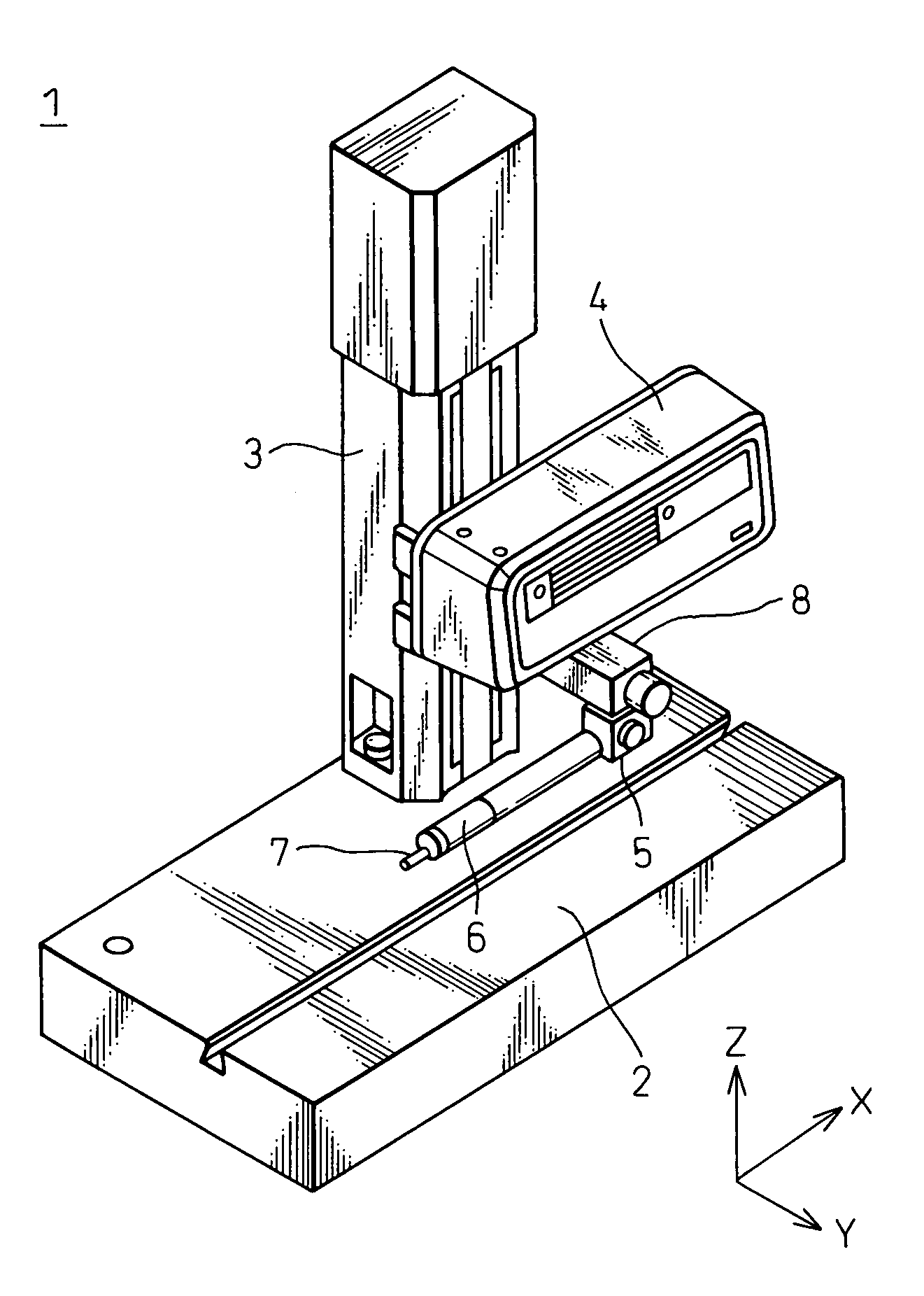
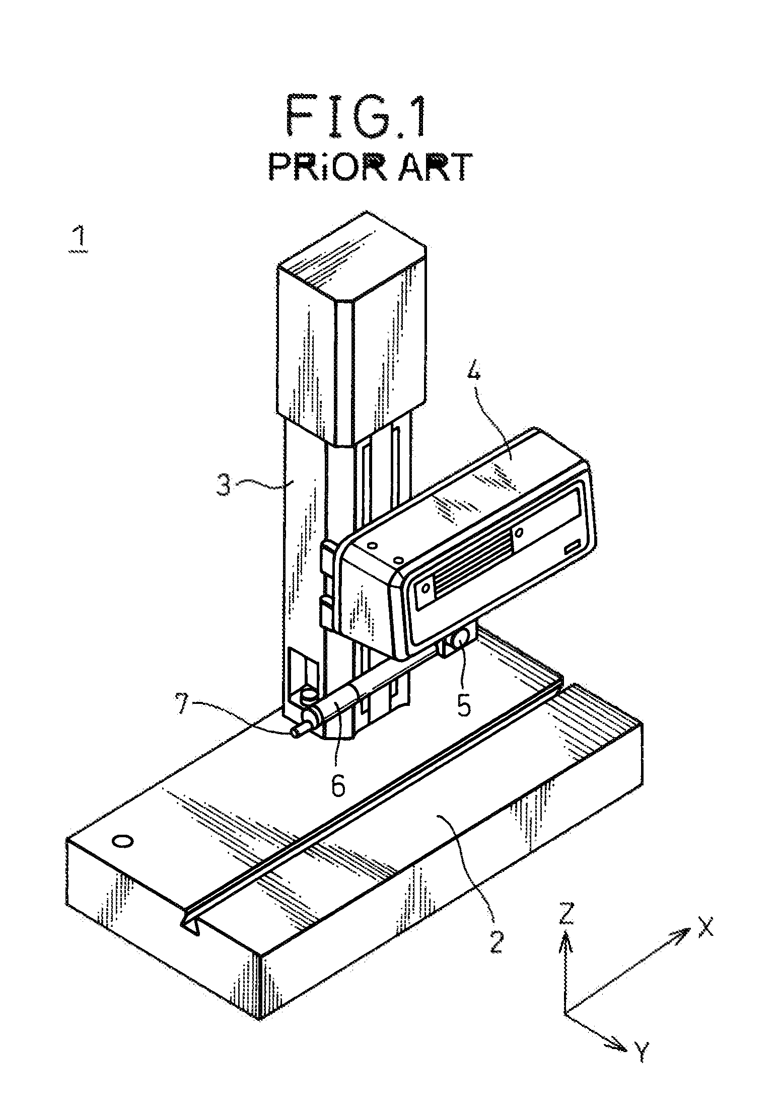
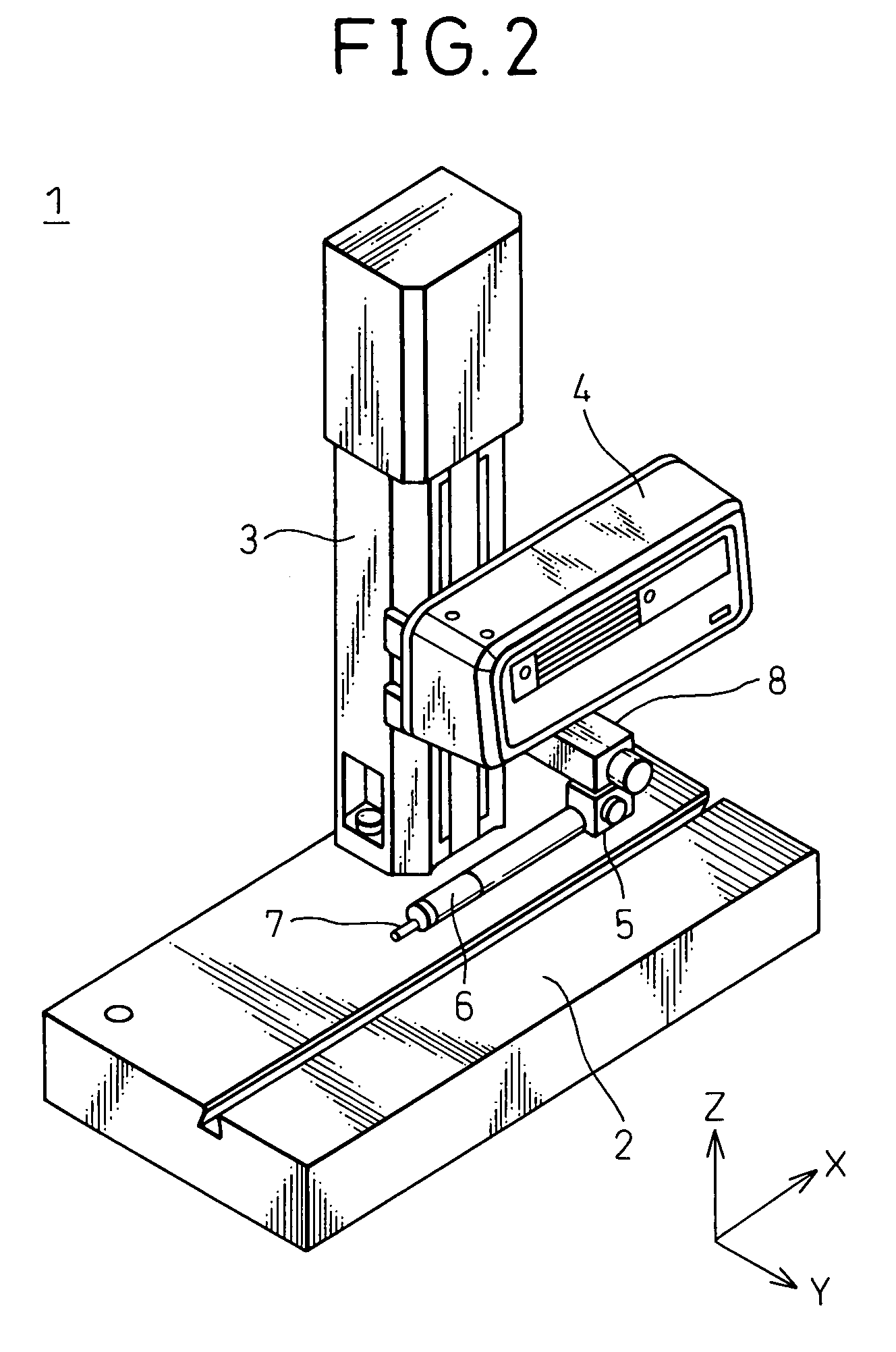
[0030]FIG. 2 is a diagram showing the basic configuration of a surface roughness / contour shape measuring apparatus according to an embodiment of the present invention. The basic configuration of the surface roughness / contour shape measuring apparatus 1 is similar to the configuration shown in FIG. 1; therefore, the functional parts similar to those in FIG. 1 are designated by the same reference numerals, and the description of such parts will not be repeated here.

[0031]As shown, in the surface roughness / contour shape measuring apparatus 1, the holder 5 for supporting the pickup 6 is connected to the driving unit 4 via a connecting member 8.

[0032]In the example of FIG. 2, the connecting member 8 is capable of moving the pickup 6 along the Y direction at right angles to the X direction which is one predesignated direction in the X-Y plane parallel to the tabl...


PUM


Abstract

The present invention provides a surface roughness / contour shape measuring apparatus that can move a probe relative to a workpiece within an orthogonal X-Y plane while employing a relatively inexpensive construction. In the surface roughness / contour shape measuring apparatus (1), the probe (6, 7) and a driving unit (4) for driving the probe (6, 7) in one predesignated direction are connected together by a connecting member (8) capable of moving the probe (6, 7) in one predesignated direction relative to the driving unit (4).

Description

CROSS-REFERENCE TO RELATED APPLICATION[0001]This application claims priority of Japanese Patent Application Number 2004-305253, filed on Oct. 20, 2004.BACKGROUND OF THE INVENTION[0002]1. Field of the Invention[0003]The present invention relates to a surface roughness / contour shape measuring apparatus and, more particular to a surface roughness / contour shape measuring apparatus for measuring the surface roughness and contour shape of a three-dimensional workpiece along two axis directions without moving the workpiece.[0004]2. Description of the Related Art[0005]A surface roughness / contour shape measuring apparatus measures the surface roughness or contour shape of a workpiece by moving a pickup equipped with a stylus along the surface of the workpiece and by converting the amount of displacement of the stylus into an electrical signal which is read into a computer or the like for processing. FIG. 1 shows the basic configuration of a prior art surface roughness / contour shape measuring...

Claims


Application Information

Patent Timeline
Patent Type & Authority Patents(United States)
IPC IPC(8): G01B5/20
CPCG01B5/28
Inventor TANIUCHI, NOBUYUKIKUBOTA, KAZUHIRO
Owner TOKYO SEIMITSU
Why Eureka
Try Eureka