Single sensor ring laser gyroscope

a laser gyroscope and single sensor technology, applied in the direction of speed measurement using gyroscopic effects, instruments, surveying and navigation, etc., can solve the problems of low readout signal (power), production cycle time, performance degradation,

Inactive Publication Date: 2008-02-12
HONEYWELL INT INC
View PDF16 Cites 50 Cited by
  • Summary
  • Abstract
  • Description
  • Claims
  • Application Information

AI Technical Summary

Problems solved by technology

Drawbacks to the known two sensor ring laser gyroscopes include performance degradation due to mode competition (near the TEM00 mode), production cycle time, cost, sensor inventory due to a need to match a normal distribution of gyroscope fringe patterns to a corresponding grid pattern on the readout sensor, low readout signal (power), and gyroscope life due to the original signal strength degrading over time.
This is particularly troublesome for transverse modes that are not discriminated against strongly by the internal body aperture.

Method used


Image

  • Single sensor ring laser gyroscope
  • Single sensor ring laser gyroscope
  • Single sensor ring laser gyroscope

Examples


Embodiment Construction

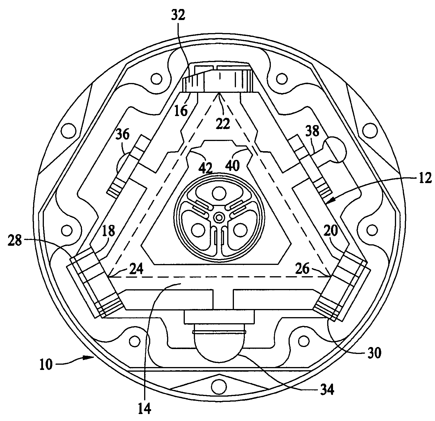
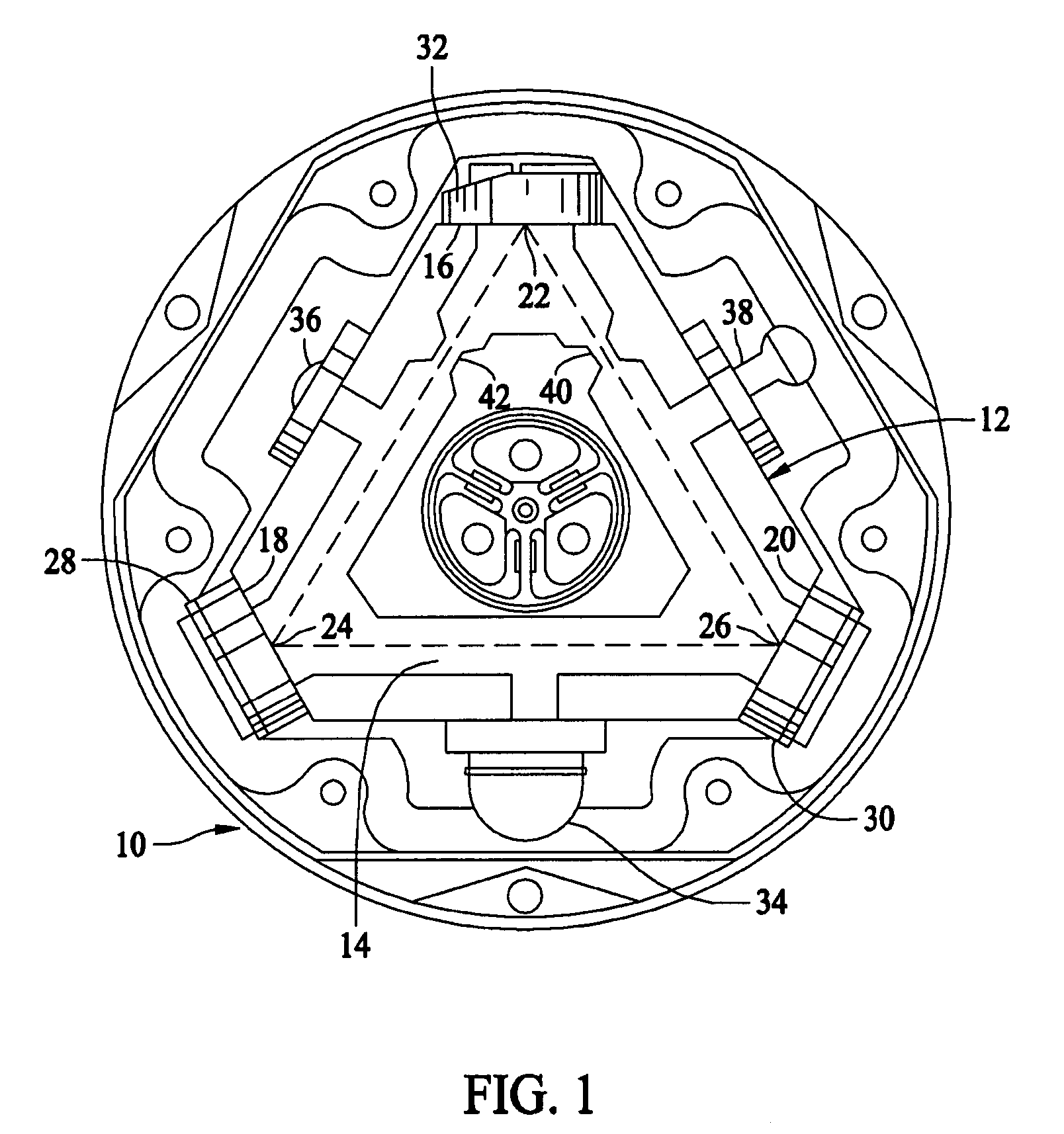
[0028]FIG. 1 is a diagram illustrating optical components and an optical path for transmitted beams within a known ring laser gyroscope 10. Ring laser gyroscope 10 includes a substantially triangular laser block 12 that provides a ring laser cavity 14 containing lasing gas. Laser block 12 includes block surfaces 16, 18, and 20 between which is an optical laser path with vertices 22, 24, and 26 at respective block surfaces 16, 18, and 20. Mirror assemblies 28, 30, and 32 are mounted to block surfaces 16, 18, and 20, respectively. Ring laser cavity 14 is filled with a lasing gas that is ignited or excited by a sufficient voltage between cathode 34 and each of anodes 36 and 38. In turn, a pair of counter-propagating laser beams travel along the optical laser path within laser cavity 14. One or more of mirror assemblies 28, 30, and 32 are transmissive, which allows a portion of the counter-propagating laser beams to pass through the mirror and onto sensors as further described below.

[00...


PUM


Abstract

A ring laser gyroscope is described which includes a laser cavity configured to provide an optical laser path for a pair of counter-propagating laser beams, an optical sensor configured to receive a portion of the energy from the counter-propagating laser beams, and a unit configured to receive outputs from the optical sensor. The unit is configured to utilize the output to generate at least a residual path length control signal, a laser intensity monitor signal, and readout signals.

Description

BACKGROUND OF THE INVENTION[0001]This invention relates generally to ring laser gyroscopes, and more specifically, to a ring laser gyroscope which utilizes a single optical sensor in the generation of output signals typically generated by ring laser gyroscopes which incorporate multiple optical sensors.[0002]A ring laser gyroscope utilizes interference of laser light within a ring optical cavity to detect changes in orientation and rate of turn. At least some known ring laser gyroscopes utilize two optical sensors, which provide signals to respective electronic circuits to generate ring laser gyroscope output signals. One such optical sensor is sometimes referred to as a laser intensity monitor (LIM) sensor, and the other optical sensor is sometimes referred to as a readout sensor.[0003]The LIM sensor and associated electronic circuitry generate at least a LIM monitor signal, a residual path length control (PLC) modulation signal, and a residual single beam signal (SBS) which are ut...

Claims


Application Information

Patent Timeline
Patent Type & Authority Patents(United States)
IPC IPC(8): G01C19/64
CPCG01C19/662G01C19/665
Inventor ZURN, BRITTAN L.BEAUDET, RICHARD G.SAVARD, THOMAS A.THIELMAN, LEROY O.THORLAND, RODNEY H.
Owner HONEYWELL INT INC
Why Eureka
Try Eureka