
Structure providing enhanced self-pinning for CPP GMR and tunnel valve heads

a technology of tunnel valve and gmr, which is applied in the field of reading heads, can solve the problems of reducing signal or dynamic range, degrading sv sensor performance, and ap-pinned layer structure being vulnerable to demagnetization, and achieve the effect of improving self-pinning

Inactive Publication Date: 2008-02-12
HITACHI GLOBAL STORAGE TECH NETHERLANDS BV
View PDF36 Cites 26 Cited by
  • Summary
  • Abstract
  • Description
  • Claims
  • Application Information

AI Technical Summary

Benefits of technology

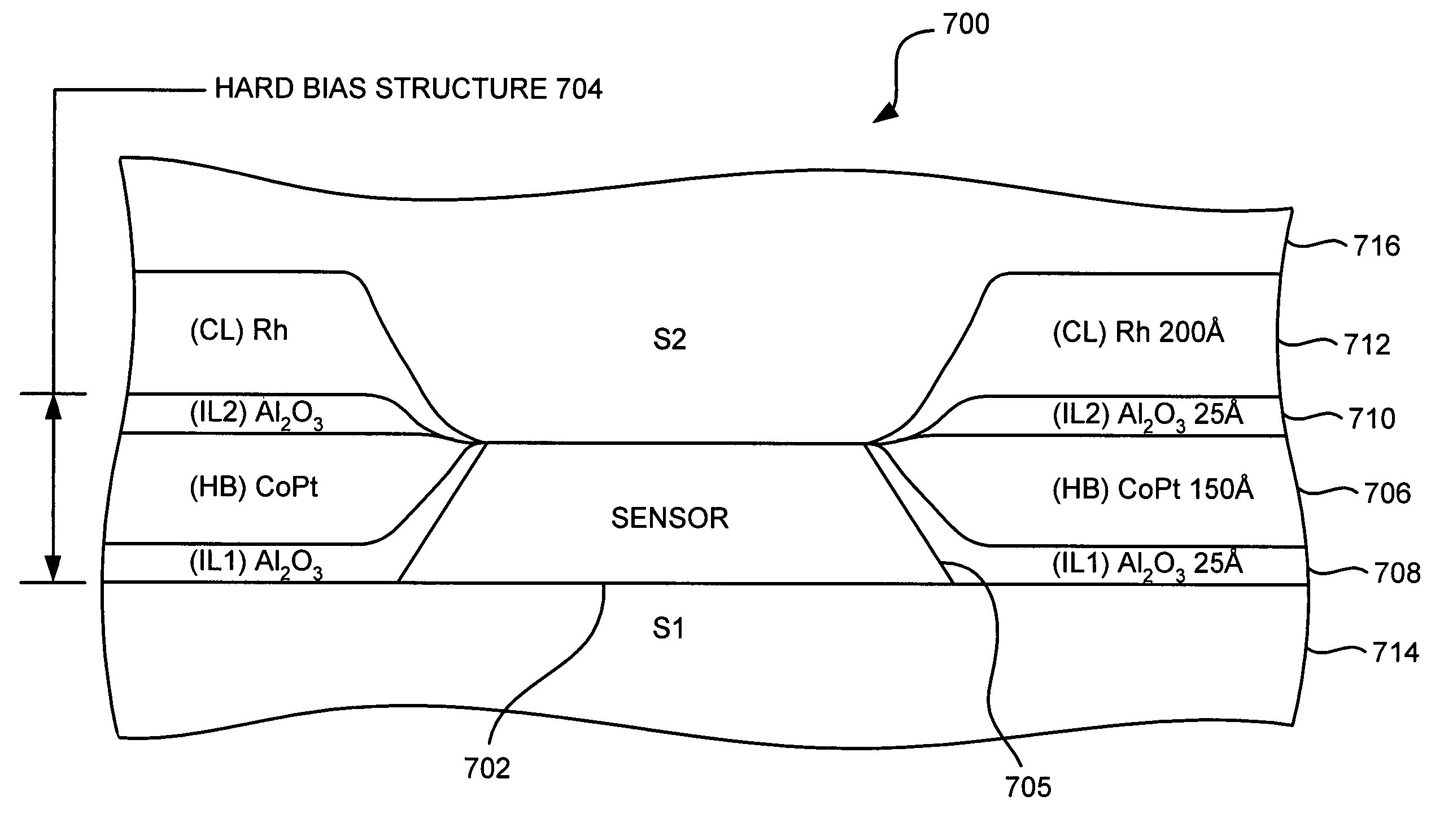
[0022]The present invention overcomes the drawbacks and limitations described above by providing a magnetic head having improved self-pinning. The head includes a sensor having an antiparallel (AP) pinned layer structure, where the AP pinned layer structure includes at least two pinned layers having magnetic moments that are self-pinned antiparallel to each other, the pinned layers being separated by an AP coupling layer. A pair of compression layers are positioned towards opposite track edges of the sensor. The compression layers provide compressive stress to the sensor.
[0024]The head may further include shield layers positioned above and below the sensor, and at least one electrically insulative layer positioned towards each of the compression layers for preventing conduction of electricity through the compression layers from one shield layer to the other shield layer and / or for preventing conduction of electricity through the compression layers from the sensor to one of the shield layers.

Problems solved by technology

Lack of magnetic saturation in the pinned layer leads to reduced signal or dynamic range.
Most commonly used AFM materials have blocking temperatures (temperature at which the pinning field reaches zero Oe) near 200° C. This means that if the temperature of the SV sensor approaches this temperature, the pinned layer magnetization can change its orientation resulting in degraded SV sensor performance.
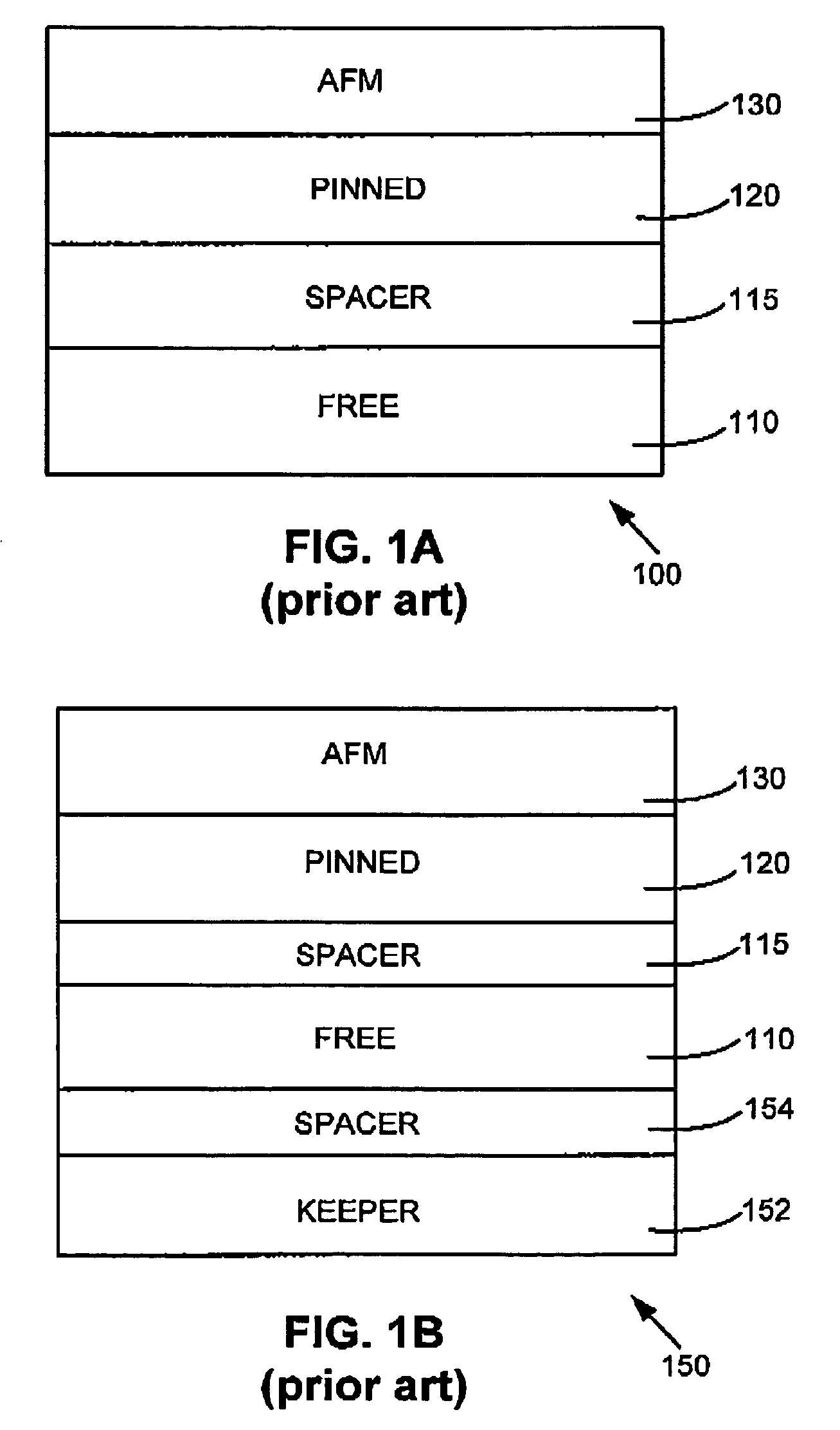
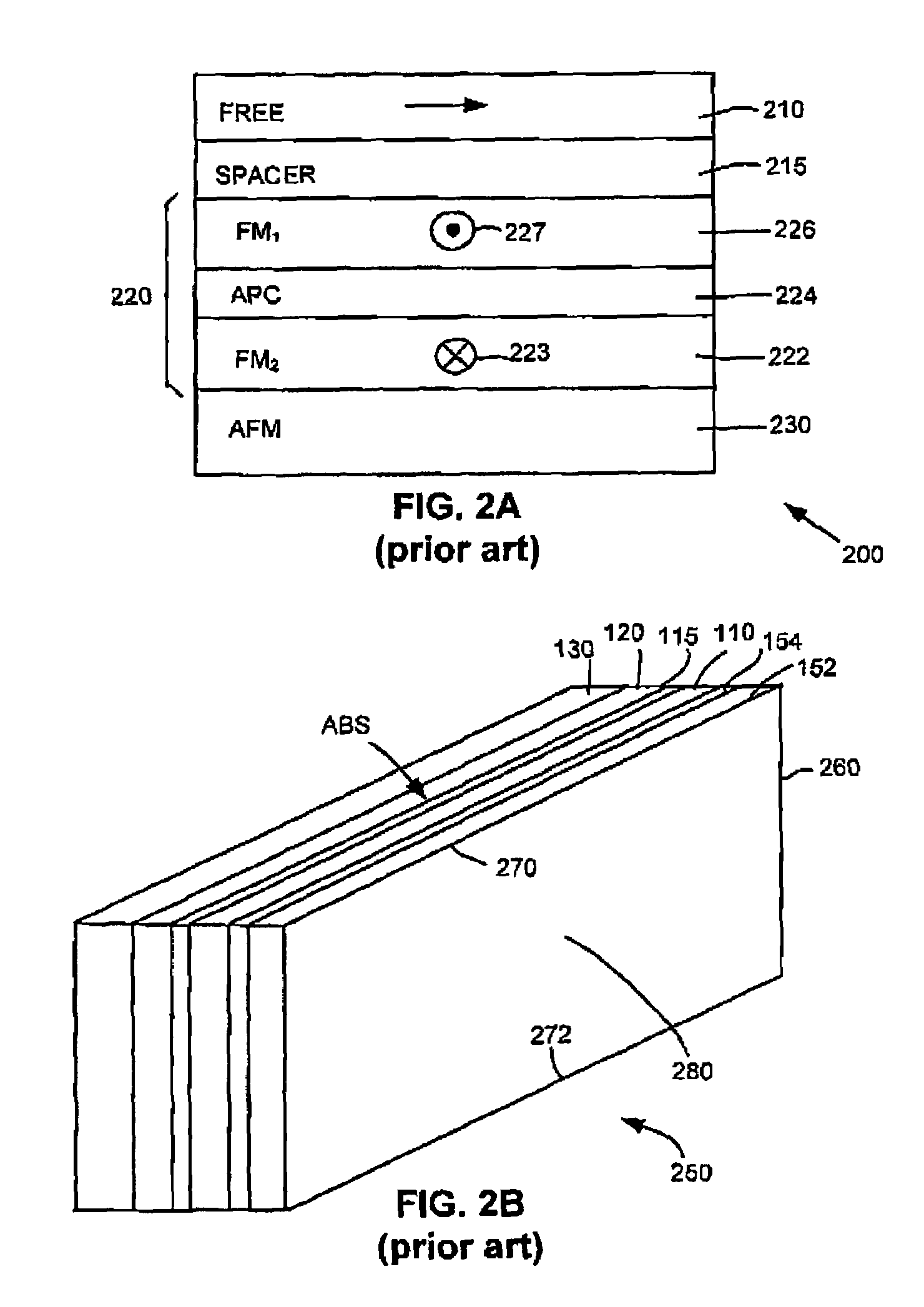
Although AP-Pinned SV sensors have large effective pinning fields because near cancellation of the magnetic moments of the two sub-layers results in a low net magnetic moment for the pinned layer, thermal stability is still a concern because the operating temperatures of these SV sensors in disk files can exceed 120° C. In addition, the AP-pinned layer structure is vulnerable to demagnetization during processing operations such as lapping.
Therefore there is a need for an SV sensor that increases the magnetic saturation of the pinned layer and reduces the sensitivity to demagnetizing fields particularly at the front and rear edges of the pinned layer stripe.
+10% readback asymmetry may not be acceptable in applications where the applied field magnetizes the free layer close to saturation.

Method used


Image

  • Structure providing enhanced self-pinning for CPP GMR and tunnel valve heads
  • Structure providing enhanced self-pinning for CPP GMR and tunnel valve heads
  • Structure providing enhanced self-pinning for CPP GMR and tunnel valve heads

Examples


Embodiment Construction

[0044]The following description is the best embodiment presently contemplated for carrying out the present invention. This description is made for the purpose of illustrating the general principles of the present invention and is not meant to limit the inventive concepts claimed herein.

[0045]Referring now to FIG. 3, there is shown a disk drive 300 embodying the present invention. As shown in FIG. 3, at least one rotatable magnetic disk 312 is supported on a spindle 314 and rotated by a disk drive motor 318. The magnetic recording on each disk is in the form of an annular pattern of concentric data tracks (not shown) on the disk 312.

[0046]At least one slider 313 is positioned near the disk 312, each slider 313 supporting one or more magnetic read / write heads 321. More information regarding such heads 321 will be set forth hereinafter during reference to FIG. 4. As the disks rotate, slider 313 is moved radially in and out over disk surface 322 so that heads 321 may access different tr...


PUM

PropertyMeasurementUnit
temperatureaaaaaaaaaa
magnetizationaaaaaaaaaa
temperaturesaaaaaaaaaa

Abstract

A magnetic head having improved self-pinning. The head includes a sensor having an antiparallel (AP) pinned layer structure, where the AP pinned layer structure includes at least two pinned layers having magnetic moments that are self-pinned antiparallel to each other, the pinned layers being separated by an AP coupling layer. A pair of compression layers are positioned towards opposite track edges of the sensor. The compression layers provide compressive stress to the sensor.

Description

FIELD OF THE INVENTION[0001]The present invention relates to magnetic heads, and more particularly, this invention relates to reading heads having a new compression layer structure that improves signal and / or pinned layer stability.BACKGROUND OF THE INVENTION[0002]The heart of a computer is a magnetic disk drive which includes a rotating magnetic disk, a slider that has read and write heads, a suspension arm above the rotating disk and an actuator arm that swings the suspension arm to place the read and write heads over selected circular tracks on the rotating disk. The suspension arm biases the slider into contact with the surface of the disk when the disk is not rotating but, when the disk rotates, air is swirled by the rotating disk adjacent an air bearing surface (ABS) of the slider causing the slider to ride on an air bearing a slight distance from the surface of the rotating disk. When the slider rides on the air bearing the write and read heads are employed for writing magnet...

Claims


Application Information

Patent Timeline
Patent Type & Authority Patents(United States)
IPC IPC(8): G11B5/39G11B5/37
CPCG11B5/37
Inventor GILL, HARDAYAL SINGH
Owner HITACHI GLOBAL STORAGE TECH NETHERLANDS BV
Learn More