Method for reconstruction of phonograph records from physical measurement

a technology of physical measurement and phonograph, applied in the field of physical measurement reconstruction of phonograph records, can solve the problems of large instantaneous velocity, large instantaneous velocity, and inability to accurately reproduce the original sound of suppression or amplification of certain frequencies

a technology of physical measurement and phonograph, applied in the field of physical measurement reconstruction of phonograph records, can solve the problems of large instantaneous velocity, large instantaneous velocity, and inability to accurately reproduce the original sound of suppression or amplification of certain frequencies

US7330414B2Inactive Publication Date: 2008-02-12CONVOLVE

Image

  • Method for reconstruction of phonograph records from physical measurement
  • Method for reconstruction of phonograph records from physical measurement
  • Method for reconstruction of phonograph records from physical measurement

Examples


Embodiment Construction

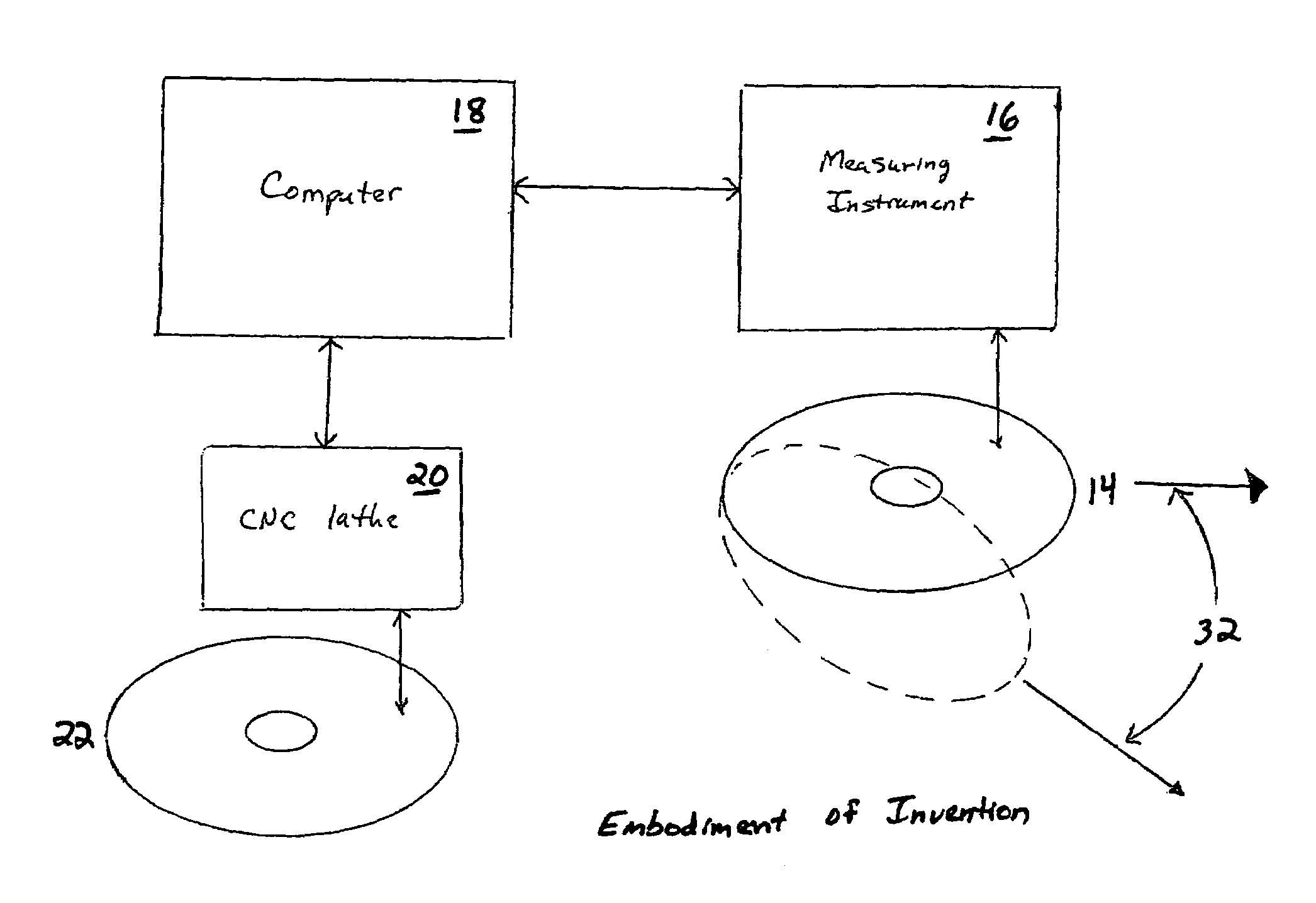
[0018]Preferred embodiments of the invention will now be described with reference to the accompanying drawings.

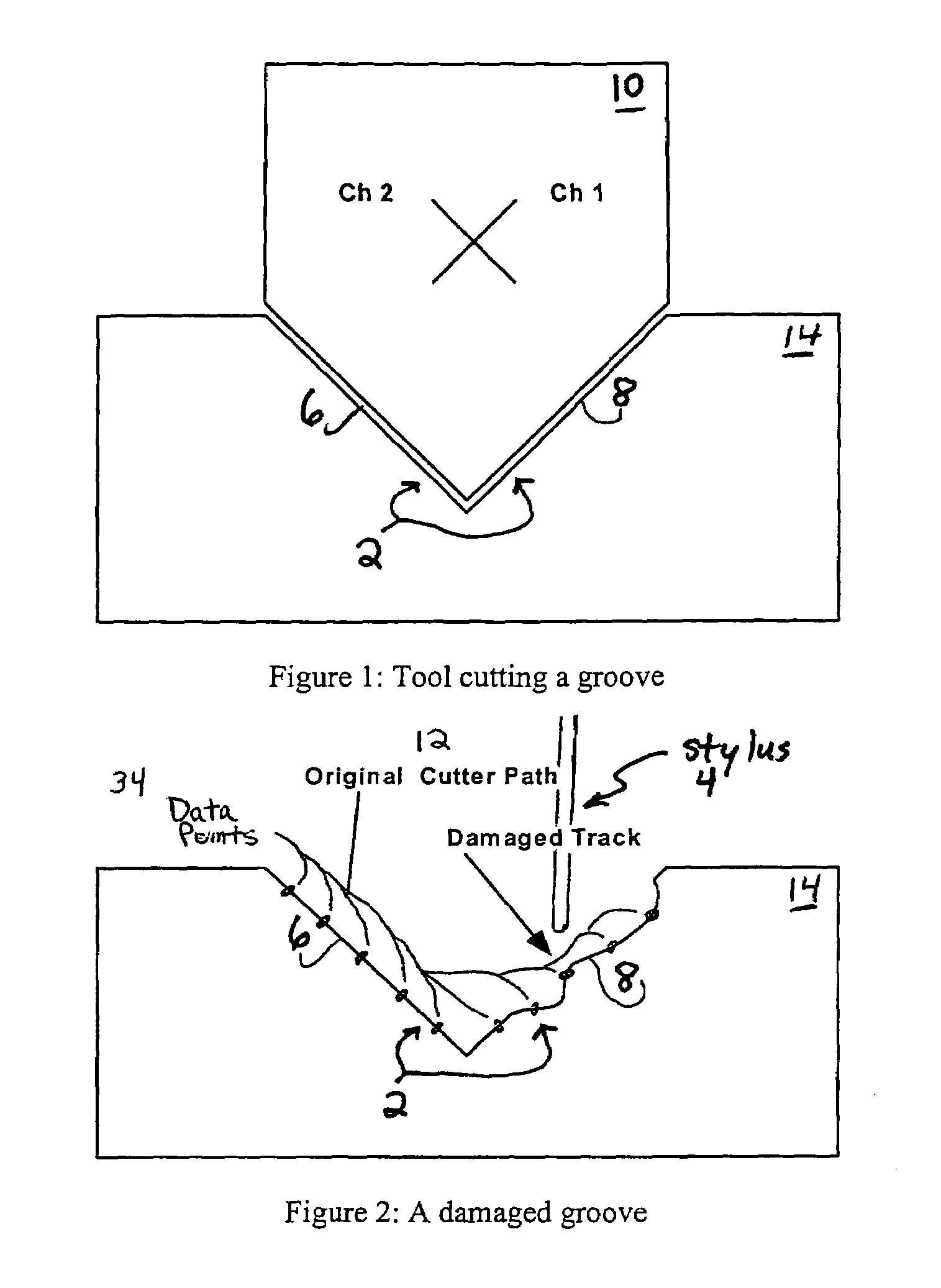
[0019]By measuring a geometry of a record groove (shown as 2 in FIG. 1 and FIG. 2), an original sound can be reconstructed in high fidelity.

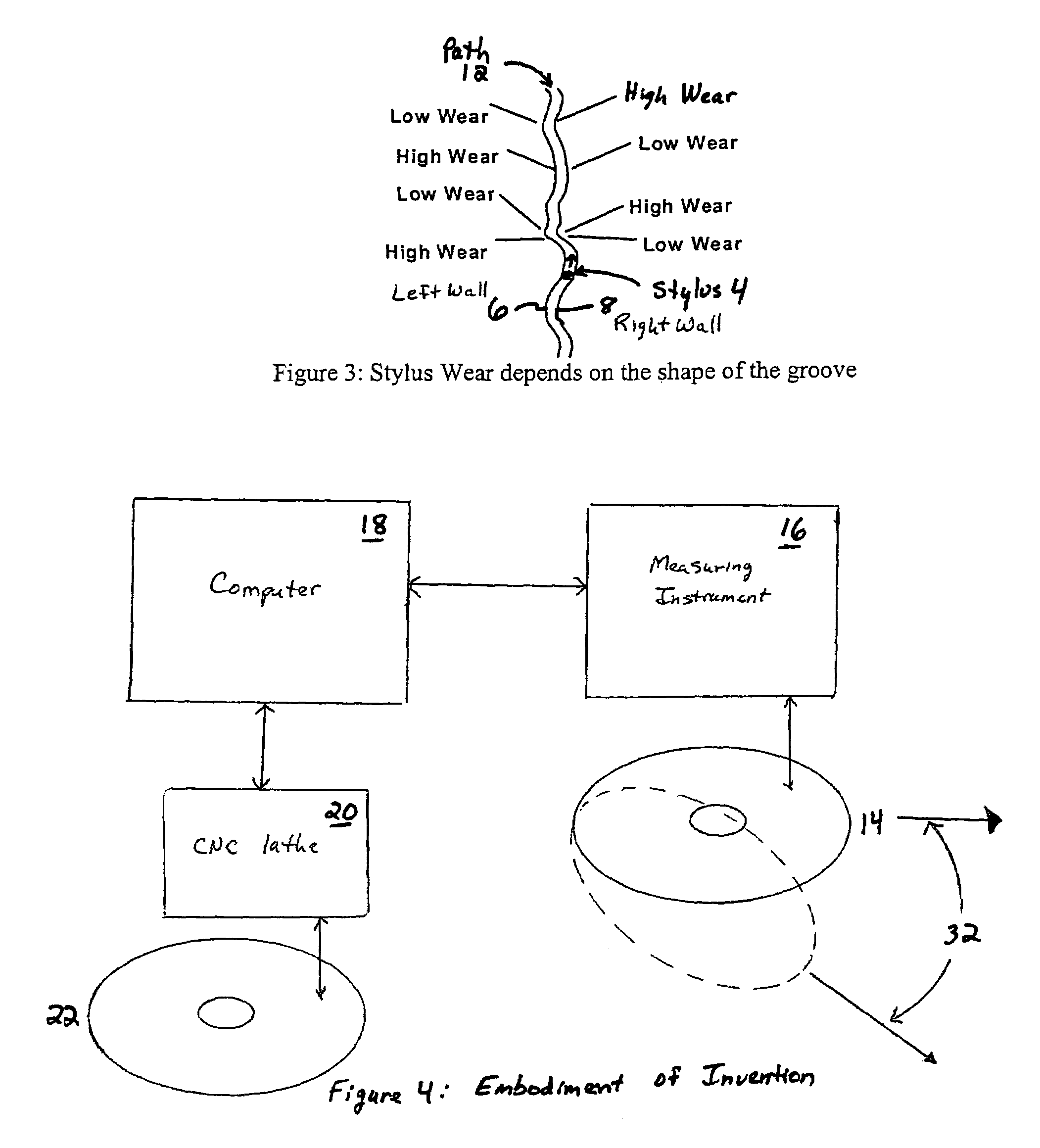
[0020]FIG. 2 shows a damaged wall 8 of a groove 2. Note that a playback stylus 4 can never track a groove wall 8 that has been damaged this much. When records wear, they do not do so uniformly. As shown in FIG. 3, if a stylus 4 tracks a groove path 12 which bends to the right, forces from the left wall 6 must push the stylus 4 over to keep it tracking the groove path 12. This results in high wear and signal loss. It is important to note that the signal loss is irrecoverable from the damaged portion of the left wall 6. Even if the left wall 6 of the groove 2 is permanently destroyed, all of the sound information is still intact in the right wall 8 of the groove 2. In conventional playback, the stylus 4 can never retrieve this information...


PUM

PropertyMeasurementUnit
angleaaaaaaaaaa
diameteraaaaaaaaaa
circumferenceaaaaaaaaaa

Abstract

A method for reconstructing the original groove configuration of a phonograph record. The methodology comprises providing an instrument for measuring the entire groove of a phonograph with an instrument in communication with a computer. The computer reconstructs the original groove configuration, using data from the measurements of the record groove. Various instrument embodiments are disclosed.

Description

[0001]This application is a continuation of pending U.S. patent application Ser. No. 09 / 732,598 filed on Dec. 7, 2000 now U.S. Pat. No. 6,829,207, which is incorporated by reference herein, which claims priority to provisional application Ser. No. 60 / 169,554 file date Dec. 8, 1999.FIELD OF THE INVENTION[0002]The present invention relates generally to a method for reconstructing the original information (i.e., sound recordings) encoded upon a phonograph record despite wear or damage to the record. The invention recognizes that most or all of the original information may be retrievable, despite the inability of a typical stylus to properly track a worn or damaged groove of the record. The invention has potential application in the fields of sound recording and record reconstruction.BACKGROUND OF THE INVENTION[0003]In the sound recording industry, there is substantial interest in restoring old recordings of vocal performances as well as instrumental and orchestral recordings.[0004]One ...

Claims


Application Information

Patent Timeline
12 Feb 2008
Publication
US7330414B2
IPC
G11B7/28; G11B3/64
CPC
G11B3/64; G11B7/28
Inventors
SINGER, NEIL C.