Involuted endovascular valve and method of construction

a technology of endovascular valves and valves, which is applied in the field of prosthetic valves, can solve the problems of lack of longevity of tissue valves, significant problems associated with both types of valves, and tend to degenerate rapidly, and achieve the effects of increasing the potential strength and durability of valves, and reducing the risk of recurren

Active Publication Date: 2008-02-19
EDWARDS LIFESCIENCES CORP
View PDF19 Cites 146 Cited by
  • Summary
  • Abstract
  • Description
  • Claims
  • Application Information

AI Technical Summary

Problems solved by technology

Unfortunately, after years of development of mechanical and tissue valves there remain significant problems associated with both types of valves.
Tissue valves offer freedom from anticoagulation therapy and the problems of bleeding, but tend to degenerate rapidly, particularly in younger patients.
The preservation, sterilization, and fixation processes currently used in tissue valve preparation are believed to contribute to the lack of longevity of tissue valves.
Although a technically demanding procedure, the Ross procedure frees the patient from anticoagulation therapy and has substantial longevity compared to other types of tissue valves.
A disadvantage of using the pulmonary valve to replace the aortic valve in the same patient is that the pulmonary valve must also be replaced.
Problems arise from lack of donor availability and size mismatches between the donor homograft and the living recipient.
Unfortunately, replacing the pulmonary valve with a homograft is associated with immunologically-mediated stenosis in some patients which limits their longevity.
Historically, it is known that a single leaflet valve design has a less efficient closure than a tri-leaflet valve.
The suboptimal function of a monocusp valve may adversely impact long-term results.
It is a drawback that the mono-cusp procedure is restricted to replace a valve at the location where the tissue flap is created.
The monocusp procedure does not provide a source for replacement of valves other than the pulmonary valve.
This procedure was attempted in three pediatric patients and abandoned due to immediate and severe aortic insufficiency in two patients.
The failure of this valve replacement procedure resulted, in part, from the extreme technical challenge for the surgeon.
As described previously, promising attempts to create a tissue valve by reconfiguring an individual's own living tissues have been problematic.
It is a drawback that these sutures are positioned in areas of high stress during the function of the valve through the cardiac cycle.
Although this valve is a simple design, it would be inefficient and difficult to use this method to reconfigure the patient's own tissues into a valvular structure.
It is a further disadvantage that this invention describes that it is placed in a catheter for deployment.

Method used


Image

  • Involuted endovascular valve and method of construction
  • Involuted endovascular valve and method of construction
  • Involuted endovascular valve and method of construction

Examples


example 1

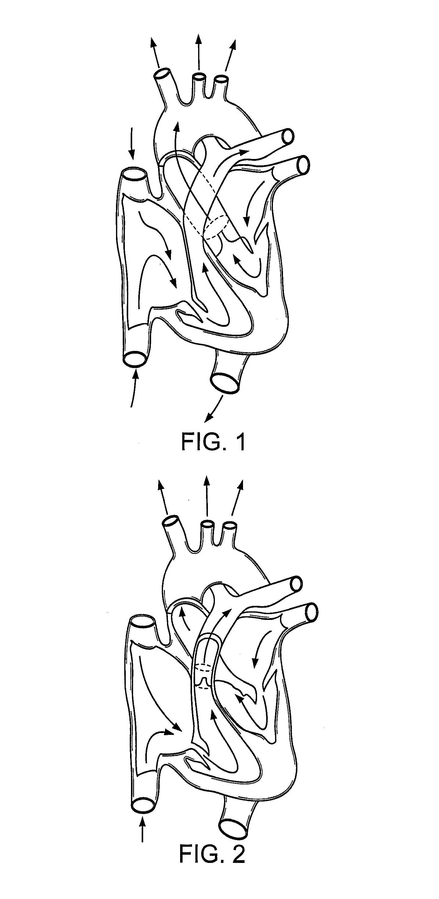
[0108]A tri-leaflet tissue valve can be constructed from the main pulmonary artery by the involution method and implanted into the aortic position in sheep (see experiment 1). This valve may also be suitable as a replacement for other valves (e.g., pulmonary valve).

Objective

[0109]An involuted cylinder valve constructed from pulmonary artery tissue and implanted in the aortic position in sheep.

Materials and Methods

[0110]From previously sacrificed donor swine (n=4, 50 kg+ / −10 kg), the main pulmonary artery and its main left and right branches were harvested. The main pulmonary artery trunk was trimmed to create a tissue cylinder of height equal to the diameter of the recipient aortic annulus. A=h≈d, where A=recipient aortic annulus diameter (mm), h=tissue cylinder height (mm), and d=tissue cylinder diameter (mm). Excess fat was trimmed from the specimen and adventitial layer was carefully peeled off as a single sheet of tissue and discarded. The tissue cylinder was incised with tree l...

example 2

[0115]A scaffold is constructed of decellularized porcine small intestinal submucosa. The involution method described above is used to form a functional three-dimensional valve. The valve is implanted into the individual and allowed to mature under in vivo conditions.

Objective

[0116]A Pulmonic Valve Replacement in Sheep Using an Involution Valve Constructed of Porcine Small Intestinal Submucosa

Materials and Methods

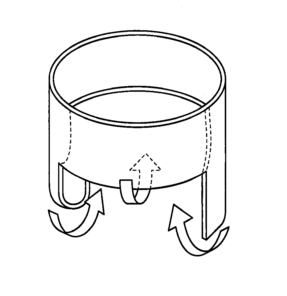
[0117]A sheet of 4-ply porcine small intestinal submucosa “SIS” (Cook, Inc.) of dimensions 68.2 mm long×20 mm wide was prepared. Two equidistant 8 mm long incisions were created extending from the free edge of the length to centerline of the material. The flat sheet was folded in half along the length with the smoother surface on the inside. A cylinder was formed by suturing the two free ends together with a running 7-0 prolene. The leaflets were secured in a perpendicular manner to the inner wall of the cylinder by “U” sutures. Two additional sheets of SIS were sutured to ...

example 3

[0121]A sheet of the patient's pericardium is harvested and formed into a valve construct using the involution method as described hereinabove at the surgical backtable. The valve construct is tested, then reimplanted into the same patient as a living autologous valve replacement.


PUM

PropertyMeasurementUnit
diameteraaaaaaaaaa
pore sizesaaaaaaaaaa

Abstract

A prosthetic tri-leaflet valve formed by involuting a portion of a tubular structure inside itself. The valve can be made by a method comprising providing a tubular segment in which three equidistant longitudinal incisions are made in one end of the tube creating three flaps which are involuted, i.e., folded, in toward the inside of the tube and the edges of the flaps secured to the inner wall of the tube to form leaflets. The tube can be formed of a single sheet of synthetic, organic or biological material and can be solid, woven, braided or the like. A braided configuration permits the valve to be annularly compressed and delivered to the site using a minimally invasive delivery mechanism, then expanded at the implantation site.

Description

CROSS-REFERENCE TO RELATED APPLICATION[0001]This application is a national phase application of, and claims priority from, International Application No. PCT / US03 / 14160, filed May 5, 2003, under 35 U.S.C. 371, which claims the benefit of priority from U.S. Provisional Patent Application No. 60 / 377,721, filed on May 3, 2002. The entire contents of both applications are incorporated herein by reference.FIELD OF THE INVENTION[0002]The present invention relates to a prosthetic valve with an involuted structure. The present invention also relates to methods and apparatus for constructing an involution valve.BACKGROUND OF THE INVENTION[0003]Since the implant of the first cardiac valvular prosthesis in the anatomic position in 1960, more than 50 different cardiac valves have been introduced over the last forty years. Unfortunately, after years of development of mechanical and tissue valves there remain significant problems associated with both types of valves.Mechanical vs. Tissue Valves[00...

Claims


Application Information

Patent Timeline
Patent Type & Authority Patents(United States)
IPC IPC(8): A61F2/24B28B1/00
CPCA61F2/2412A61F2/2415A61F2/2418
Inventor WHITE, JENNIFER K.
Owner EDWARDS LIFESCIENCES CORP
Why Eureka
Try Eureka