
Head supporting mechanism including two load beams with ribs overlapped with each other

a support mechanism and load beam technology, applied in the direction of head support, record information storage, instruments, etc., can solve the problems serious problem of low impact resistance, and high probability of excessive impact, so as to enhance the impact resistance

Inactive Publication Date: 2008-02-19
TDK CORPARATION
View PDF5 Cites 9 Cited by
  • Summary
  • Abstract
  • Description
  • Claims
  • Application Information

AI Technical Summary

Benefits of technology

The present invention provides a suspension and head supporting mechanism for a disk drive device with improved impact resistance. The suspension includes a flexure with elasticity for supporting a head slider and two load beams that are reinforced at both ends with ribs. The load beams are overlaid with each other and fixed to the suspension, and a load generating means is used to press the head slider through the load support points. The head supporting mechanism includes a support arm fixed to a horizontally-rotating bearing means, which can be rotated in a parallel direction with the recording medium surface. The invention also provides a plurality of recording media and a common horizontally-rotating bearing means for rotating the support arms and suspensions of multiple head supporting mechanisms in a parallel direction with the surfaces of the recording media.

Problems solved by technology

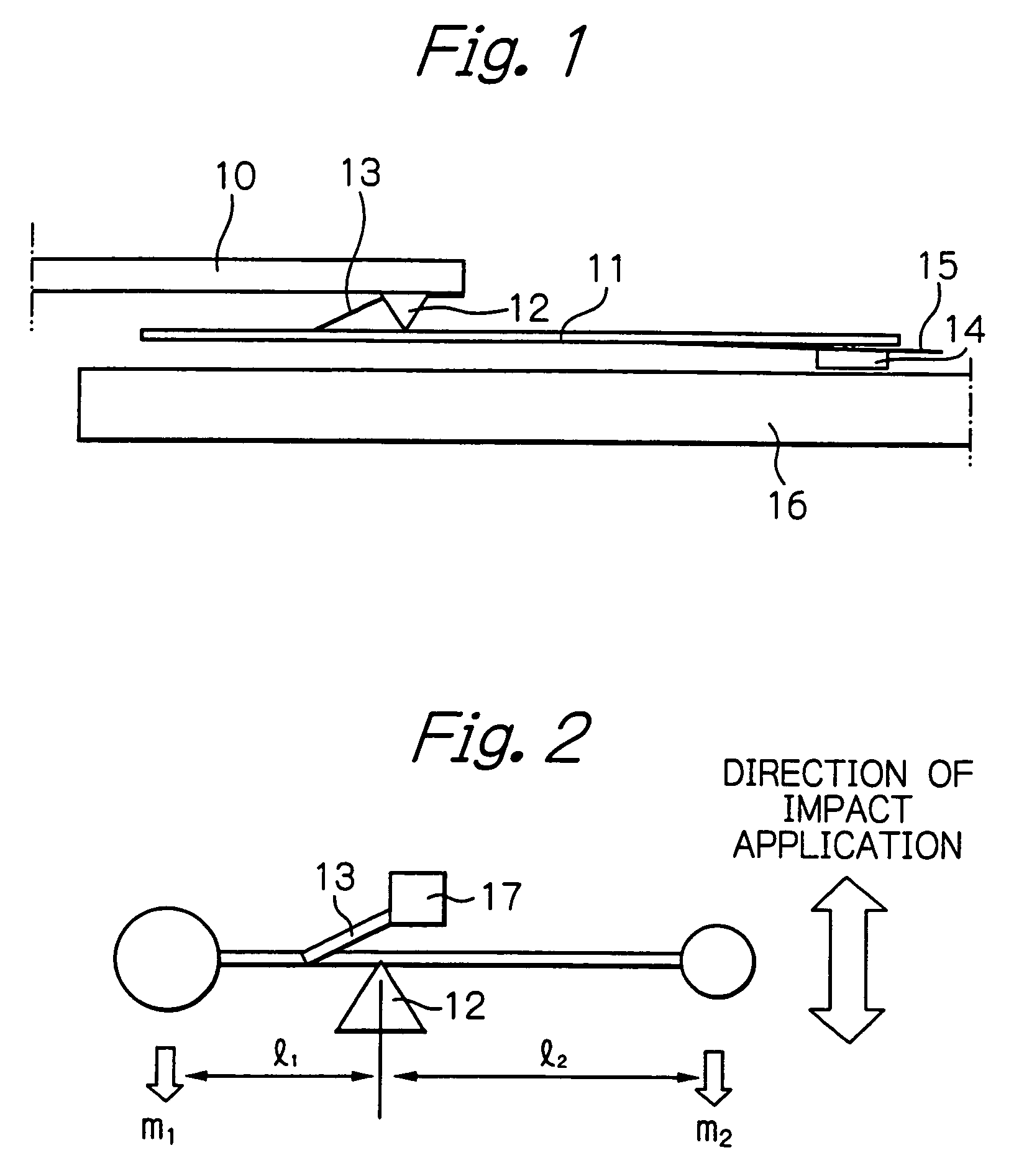
The cantilever structure has merits in a stabilization of a load applied to the magnetic head slider and a space saving, however it has a serious problem of a low impact-resistance.
However, to a magnetic disk drive device with 2.5-inch disk mounted to a notebook computer, an excessive impact is likely to be applied, so the low impact-resistance becomes a serious problem.
However, because an arm length becomes large in case of a magnetic disk drive device with larger-radius disk such as 1.8-inch or 2.5-inch disk, it is difficult to hold the impact-resistance sufficiently.
Further, because the HAA has a structure balanced by the VCM, it is impossible to construct a magnetic disk drive device with a plurality of the HAAs overlapped.
However, the ribs cannot be made longer than the whole length of the load beam, and a height limit of the ribs is imposed by need to keep clearance between the HAA and the magnetic disk.
Therefore, it is seriously difficult to heighten the first bend-mode frequency in the conventional HAA.
Consequently, quite difficult is to enhance the impact-resistance.

Method used


Image

  • Head supporting mechanism including two load beams with ribs overlapped with each other
  • Head supporting mechanism including two load beams with ribs overlapped with each other
  • Head supporting mechanism including two load beams with ribs overlapped with each other

Examples


Embodiment Construction

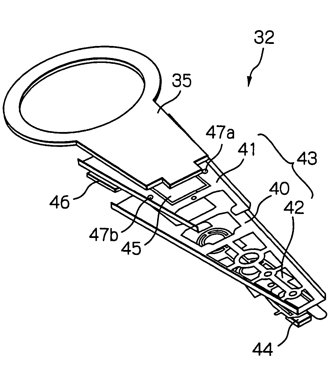
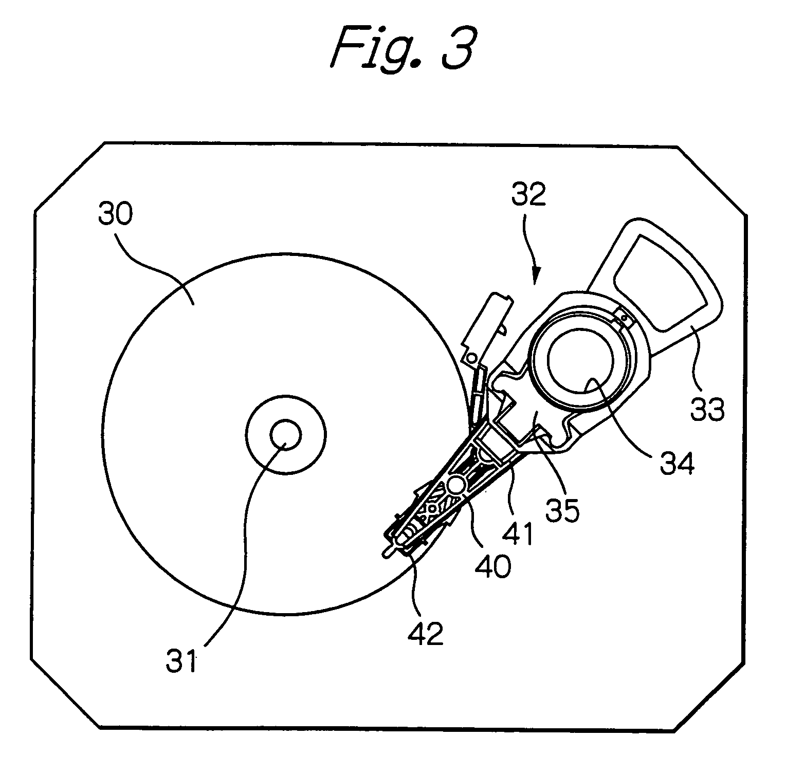
[0043]FIG. 3 shows a front view schematically illustrating a structure of a main part of a magnetic disk drive device in an embodiment of the present invention, FIG. 4 shows an exploded perspective view illustrating an HAA mounted to the magnetic disk drive device shown in FIG. 3, taken from above (from the opposite side to a side where the magnetic head slider is fixed), FIG. 5 shows an exploded perspective view illustrating the HAA, taken from below (from the side where the magnetic head slider is fixed), and FIG. 6 shows a perspective view illustrating a first and a second load beams in the HAA. In these figures, wiring patterns are omitted to be shown.

[0044]In FIG. 3, reference numeral 30 denotes a single magnetic disk with one inch diameter, rotating around a axis 31, 32 denotes an HAA where a magnetic head slider faced to a surface of a magnetic disk 30 is fixed at a front end section of the HAA and a VCM coil part 33 is fixed at a rear end section of the HAA, and 34 denotes a...


PUM

PropertyMeasurementUnit
diameteraaaaaaaaaa
thickaaaaaaaaaa
thickaaaaaaaaaa

Abstract

A suspension is provided, which comprises: a flexure with elasticity for supporting a head slider having at least one head element; a first load beam having first ribs for reinforcement at both side ends of the first load beam, for supporting the flexure; and a second load beam having second ribs for reinforcement at both side ends of the second load beam, at least a part of the second load beam being overlapped with the first load beam and being fixed to the first load beam, at least a part of the first and second ribs being overlapped with each other.

Description

PRIORITY CLAIM[0001]This application claims priority from Japanese patent application No. 2003-416132, filed on Dec. 15, 2003, which is incorporated herein by reference.BACKGROUND OF THE INVENTION[0002]1. Field of the Invention[0003]The present invention relates to a suspension, a head supporting mechanism having a combination of the suspension and a support arm, a head arm assembly (HAA) having the head supporting mechanism with a flying type head slider supporting a write and / or a read head element such as a thin-film magnetic head or an optical head, and a disk drive device with the HAA.[0004]2. Description of the Related Art[0005]In a magnetic disk drive device, a thin film magnetic head for writing magnetic information into and / or reading magnetic information from a magnetic disk is in general formed on a magnetic head slider flying in operation above the rotating magnetic disk. The magnetic head slider is fixed at a front end section of an HAA.[0006]The HAA mainly includes a m...

Claims


Application Information

Patent Timeline
Patent Type & Authority Patents(United States)
IPC IPC(8): G11B5/55G11B21/21G11B5/48G11B21/02G11B21/20
CPCG11B5/4826G11B5/4833
Inventor WADA, YOSHIMITSUWADA, TAKESHIHONDA, TAKASHIHIGUCHI, YOSHIHISA
Owner TDK CORPARATION
Learn More