Acoustic transducer with mechanical balancing
a transducer and mechanical technology, applied in the field of transducers, can solve the problems of reducing the mass of the cone, limiting the ability of the cone to vibrate at high frequencies, and limiting the ability of the cone to vibrate at high frequencies, and achieve the effect of a wider array of sound waves
- Summary
- Abstract
- Description
- Claims
- Application Information
AI Technical Summary
Benefits of technology
Problems solved by technology
Method used
Image
Examples
first embodiment
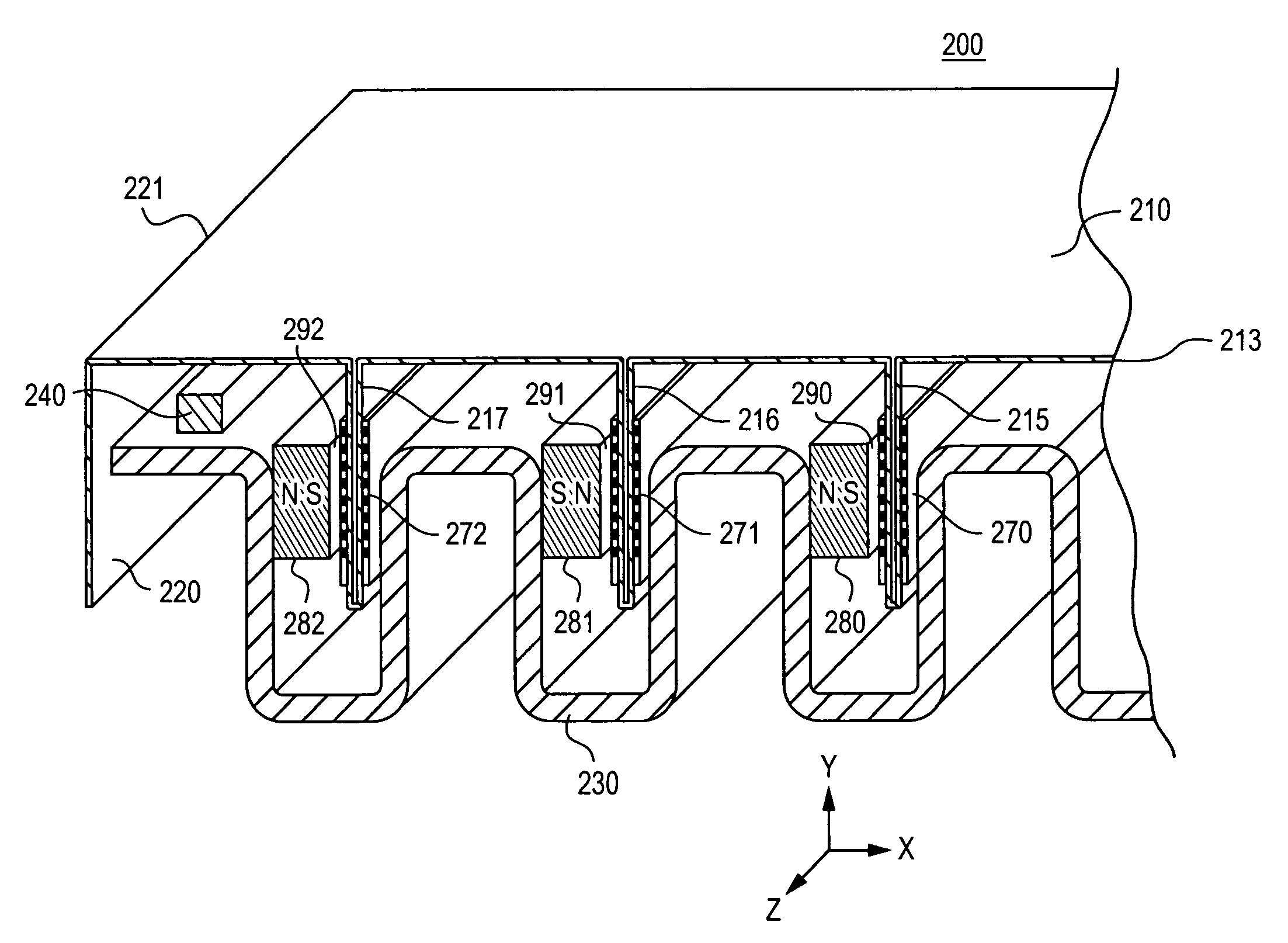
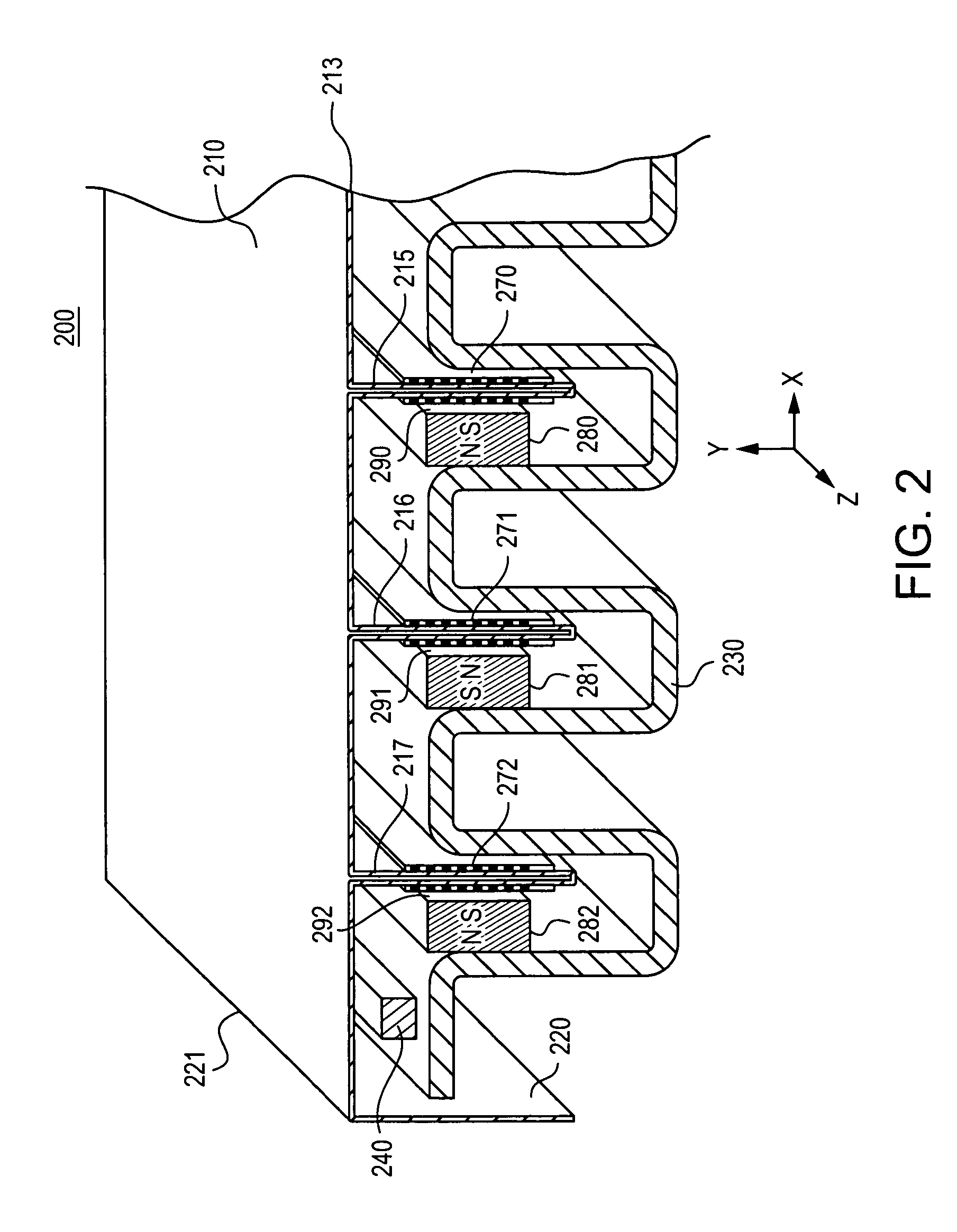
[0044]FIG. 2 is a perspective view of a low-profile transducer 200. The low-profile transducer 200 includes a frame 230; a diaphragm 210 having a perimeter 221, a substantially planar projection surface 213, one or more side surfaces 220, fins 215, 216, and 217 mounted substantially perpendicular to the projection surface 213; stationary magnets 280, 281, and 282, magnetic gaps 290, 291, and 292; voice coils 270, 271, and 272, and a pliable surround 240. The voice coils 270, 271, and 272 are mounted on the fins and reside partially in the magnetic gaps. The low-profile transducer 200 may incorporate these elements in a way that offers the energy efficiency of a cone-type transducer with the reduced depth of a planar transducer. While a particular configuration is shown, the low-profile transducer 200 may have other configurations including those with fewer or additional components.
[0045]The frame 230 may be substantially crenellated or corrugated in shape, as shown. The frame 230 ma...
second embodiment
[0065]FIG. 8 is a cross-sectional view of a low-profile transducer 800. The low-profile transducer 800 includes a crenellated ferromagnetic frame 830, a rigid diaphragm 810 having a substantially planar projection surface 813, stationary magnets 880, magnetic gaps 890; voice coils 870; and a pliable surround 840. The diaphragm 810 is made of a substantially rigid material, with voice coils 870 mounted onto the diaphragm and extending away from the diaphragm. The voice coils 870 are preferably mounted in a direction extending perpendicularly away from the surface of the diaphragm 810, and reside partially in the magnetic gaps 890 formed by the magnets 880 and the frame 830. The stationary magnets 880 are attached to a portion of the frame 830 extending in the z-direction, with poles aligned in the x-direction, parallel to the plane of the substantially planar projection surface 813. The magnetic gaps 890 may be formed adjacent to poles of the stationary magnets 880. The magnets may b...
third embodiment
[0067]FIG. 9 is a cross-sectional view of a low-profile transducer 900. The low-profile transducer 900 includes a crenellated non-ferromagnetic frame 930, a rigid diaphragm 910, stationary magnets 983, 985, 987, and 989, magnetic gaps 990, voice coils 970, and a pliable surround 940.
[0068]The bottom of the frame may have one or more grooves 937 and sides 935. The diaphragm 910 may be made of a substantially rigid material, with voice coils 970 mounted onto the diaphragm and extending away from the diaphragm. The diaphragm may be operatively attached to sides 935 of the frame by the pliable surround 940.
[0069]The low-profile transducer shown in FIG. 9 uses grooves 937 as a technique for extending a range of motion of the voice coils 970. Grooves 937 may be used in a variety of embodiments of a low-profile transducer to accommodate the excursion of the voice coils.
[0070]At least two stationary magnets 987 and 989 are used to form the magnetic gaps 990 between closely-spaced opposing m...
PUM
 Abstract
Description
Claims
Application Information
 - R&D
- Intellectual Property
- Life Sciences
- Materials
- Tech Scout
- Unparalleled Data Quality
- Higher Quality Content
- 60% Fewer Hallucinations
Browse by: Latest US Patents, China's latest patents, Technical Efficacy Thesaurus, Application Domain, Technology Topic, Popular Technical Reports.
© 2025 PatSnap. All rights reserved.Legal|Privacy policy|Modern Slavery Act Transparency Statement|Sitemap|About US| Contact US: help@patsnap.com


