Log splitter

a splitter and log technology, applied in the field of splitters, can solve the problems of unpredictably lateal or vertical slip of logs

Active Publication Date: 2008-02-26
PARADISE ANTHONY
View PDF7 Cites 13 Cited by
  • Summary
  • Abstract
  • Description
  • Claims
  • Application Information

AI Technical Summary

Problems solved by technology

If that tension holding the log in place against the push plate is exceeded by the force vector directed outward exerted by the ram, the log will slip unpredictably laterally or vertically across the push plate face and may actually be ejected unexpectedly outwardly from the desired position at the center of the push plate.
This unexpected slippage and ejection of the log from the machine can impact the operator or a bystander, potentially causing injury.

Method used


Image

  • Log splitter
  • Log splitter
  • Log splitter

Examples


Embodiment Construction

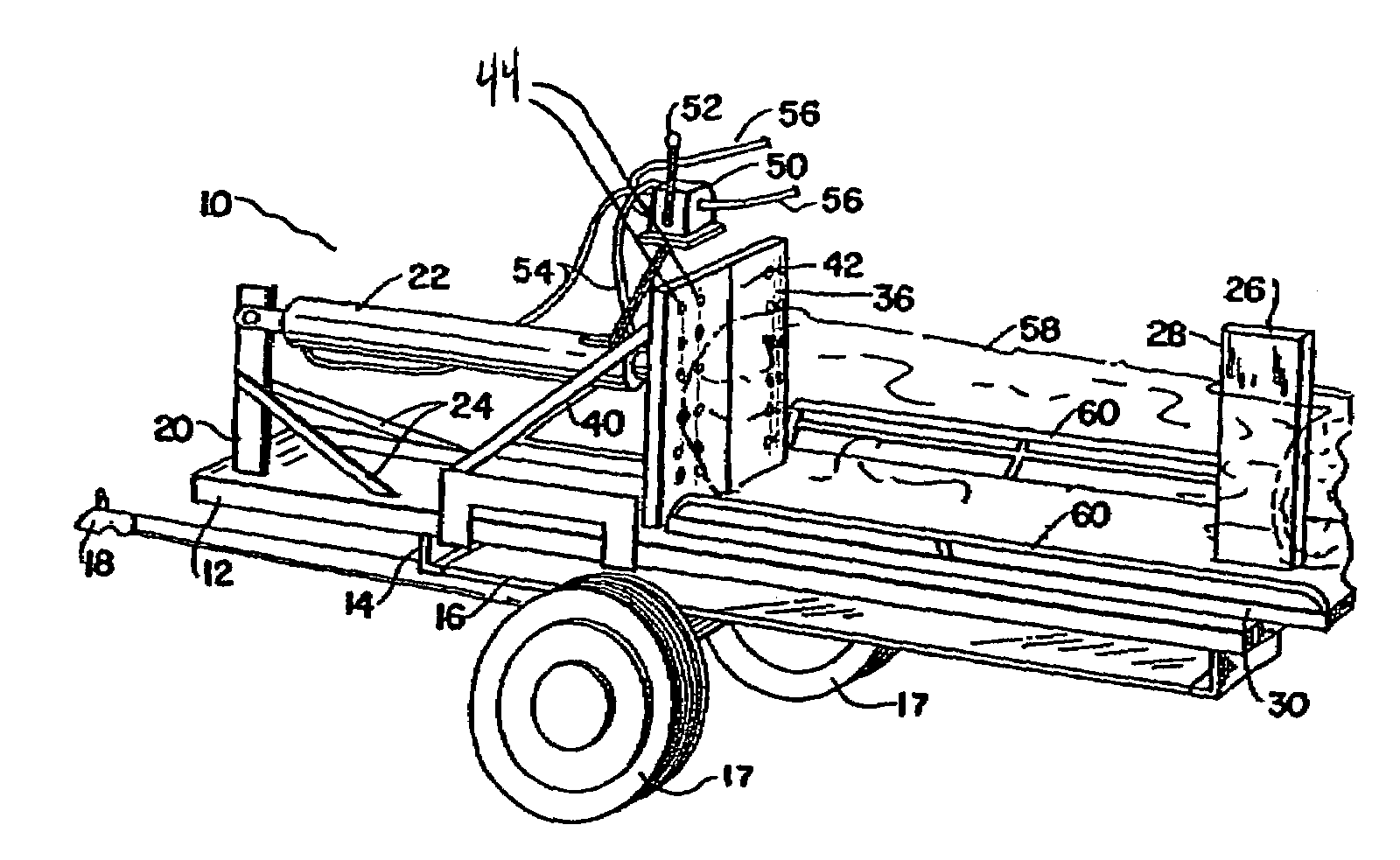
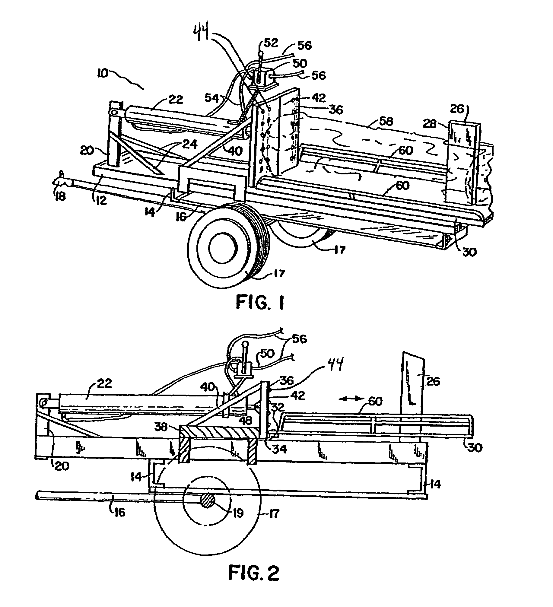
[0017]With reference to the drawing, There is shown and illustrated a log splitter constructed in accordance with the principles of the invention and designated generally by reference character 10.

[0018]The log splitter 10 includes a frame 12 and sub-frame assembly 16, secured to the frame by members 14, to an axle 19 having wheels 17 mounted thereon and fixed. A hitch 18 for a trailer mount is secured to the sub-frame assembly 16.

[0019]A bracket 20 is welded or otherwise fixed to one end of the frame 12 and supports one end of a hydraulic cylinder 22. Braces 24 are welded to a bracket 20 and to the frame 12.

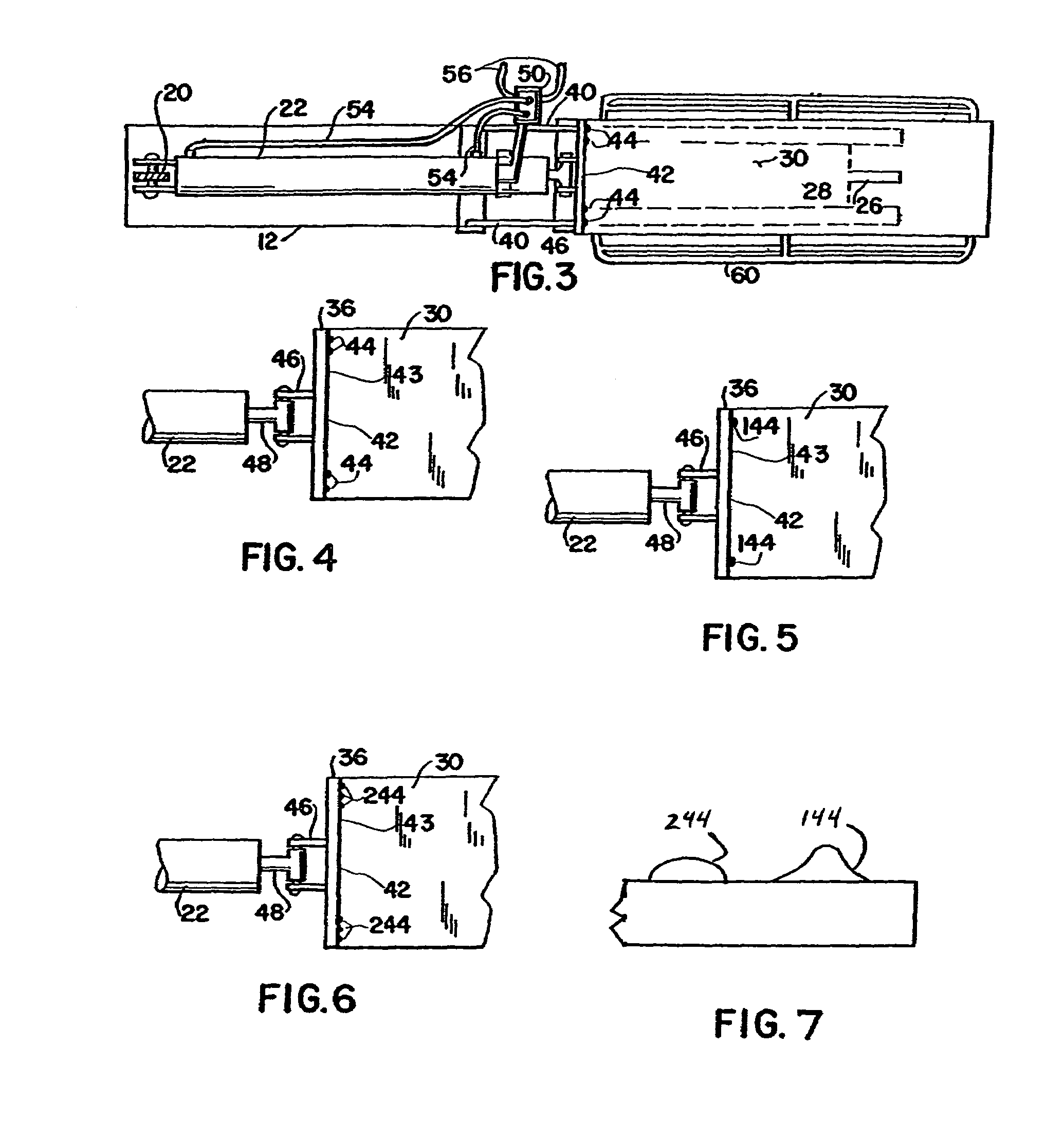
[0020]A vertical splitting blade 26 is mounted to the other end of the frame 12. The splitting blade 26 has a generally wedge shaped splitting edge 28. The splitting blade 26 can take many suitable shapes as is well known in the art. The splitting edge 28 is oriented vertically and its line of travel takes it during the splitting stroke to a centerline 42 which is the imaginary ...


PUM


Abstract

A self-contained, or externally actuated, hydraulic log splitter which includes a frame on which is slidably mounted an assembly of a specially designed push plate secured at one end to a reversible hydraulic cylinder and at the other to a splitting table carrying logs which is pushed against a straight blade to split the logs. A plurality of lines of discrete nubs are integrally a part of the push plate along a majority of its entire height and positioned substantially parallel to the straight blade and spaced away from the edge of the push plate. These nubs to provide specialized and improved gripping of log segments as they are split thereby minimizing the tendency of the split log segments to fly away from the splitter. An electric or gas engine driving an hydraulic pump or the hydraulic system of a tractor is connected to drive the reversible hydraulic cylinder.

Description

FIELD OF THE INVENTION[0001]This invention relates generally to a splitting machine for splitting logs.BACKGROUND OF THE INVENTION[0002]Log splitters are in common use that support a log between a ram and a wedge shaped splitting blade and where a ram with a push plate engages one end of the log and moves the log into forceful engagement with the sharp edge of the splitting blade and continues the movement of the log relative to the blade to effect a splitting of the log. In such log splitters the sharp edge of the blade penetrates the end of the log and as the log continues to move relative to the blade the side surfaces of the wedge will force the log to split. During the splitting process the log is held in place by the tension created by the force of the push plate against the log end. If that tension holding the log in place against the push plate is exceeded by the force vector directed outward exerted by the ram, the log will slip unpredictably laterally or vertically across ...

Claims


Application Information

Patent Timeline
Patent Type & Authority Patents(United States)
IPC IPC(8): B27L7/06
CPCB27L7/00B27L7/06
Inventor PARADISE, ANTHONY
Owner PARADISE ANTHONY
Why Eureka
Try Eureka