
Vehicle headlamp

a headlamp and vehicle technology, applied in the direction of point-like light sources, lighting and heating apparatuses, transportation and packaging, etc., can solve the problems of large quantity of lost light, loss of light which cannot contribute to distributed light projection forward, and loss of light which cannot contribute to distributed ligh

Inactive Publication Date: 2008-02-26
KOITO MFG CO LTD
View PDF5 Cites 11 Cited by
  • Summary
  • Abstract
  • Description
  • Claims
  • Application Information

AI Technical Summary

Benefits of technology

The present invention provides a vehicle headlamp that can increase the output of light without changing the output of the light source. The headlamp includes a first main reflector, a second main reflector, a shade, and a projection lens. The first main reflector reflects light emitted from the light source towards the optical axis, while the second main reflector reflects the light emitted from the light source towards a different direction. The shade cuts off a part of the light reflected by the first main reflector to form a cut-off line. The projection lens forwards the light that has passed the shade. The headlamp may also include additional sub-reflectors for further reflecting the light emitted from the light source. The arrangement of the sub-reflectors around the first main reflector allows for effective projection of light forward of the vehicle without improving the output of the light source. The sub-reflectors can also be set in different manners to enhance side or far distance visibility.

Problems solved by technology

However, for example, the light which is incident on the lower side of the reflector and cut by the shade results in the lost light which cannot contribute to distributed light to be projected forward.
Further, the light which is not incident on the reflector but goes outward directly from the light source or the light which is incident on the area other than the reflector and makes diffused reflection within the lamp unit results in the lost light which cannot contribute to distributed light.
Thus, the general projector type lamp unit makes a large quantity of lost light which cannot contribute to the distributed light to be projected forward.

Method used


Image

  • Vehicle headlamp
  • Vehicle headlamp
  • Vehicle headlamp

Examples


Embodiment Construction

[0029]Embodiments of the invention will be described with reference to the accompanying drawings.

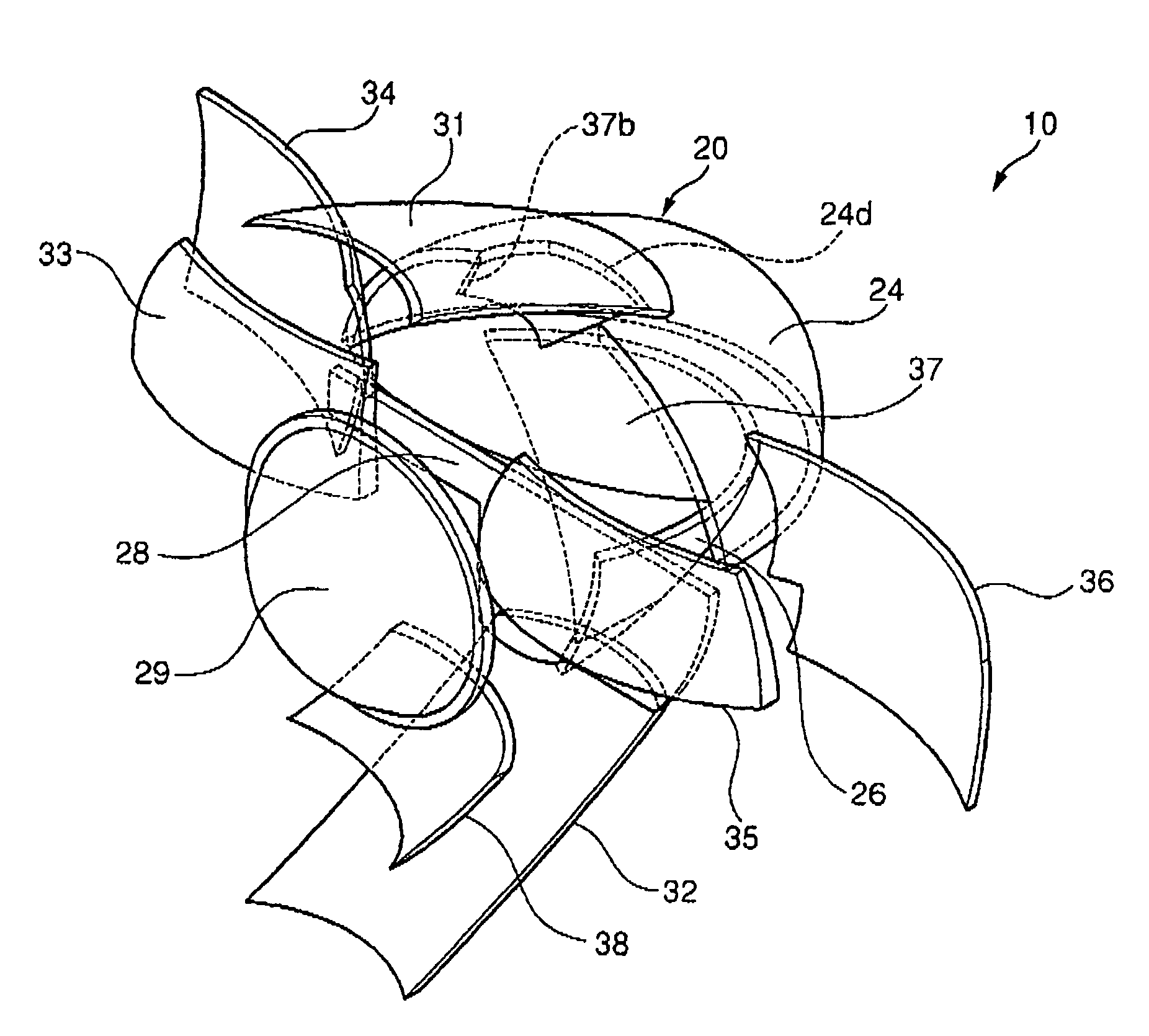
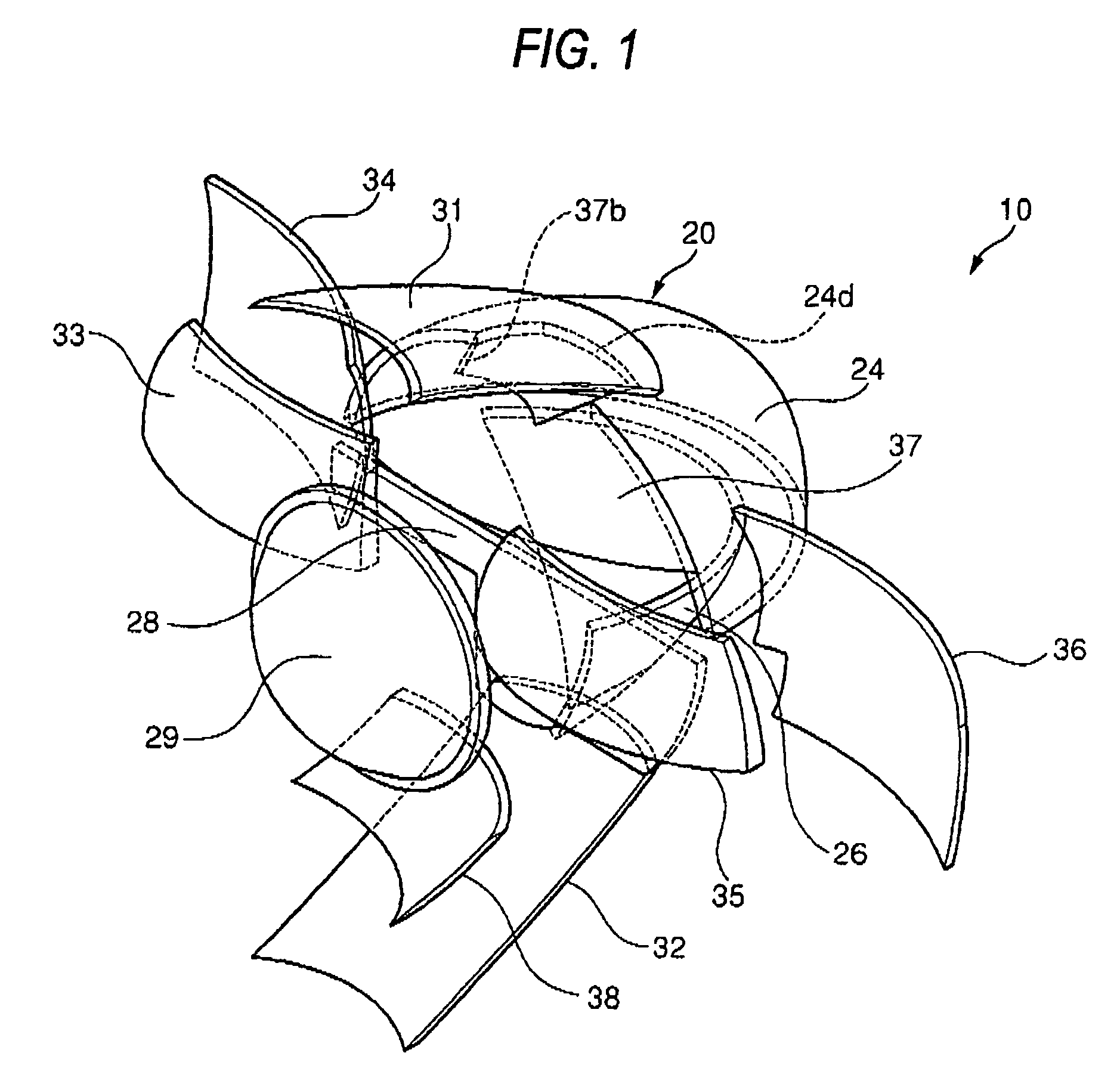
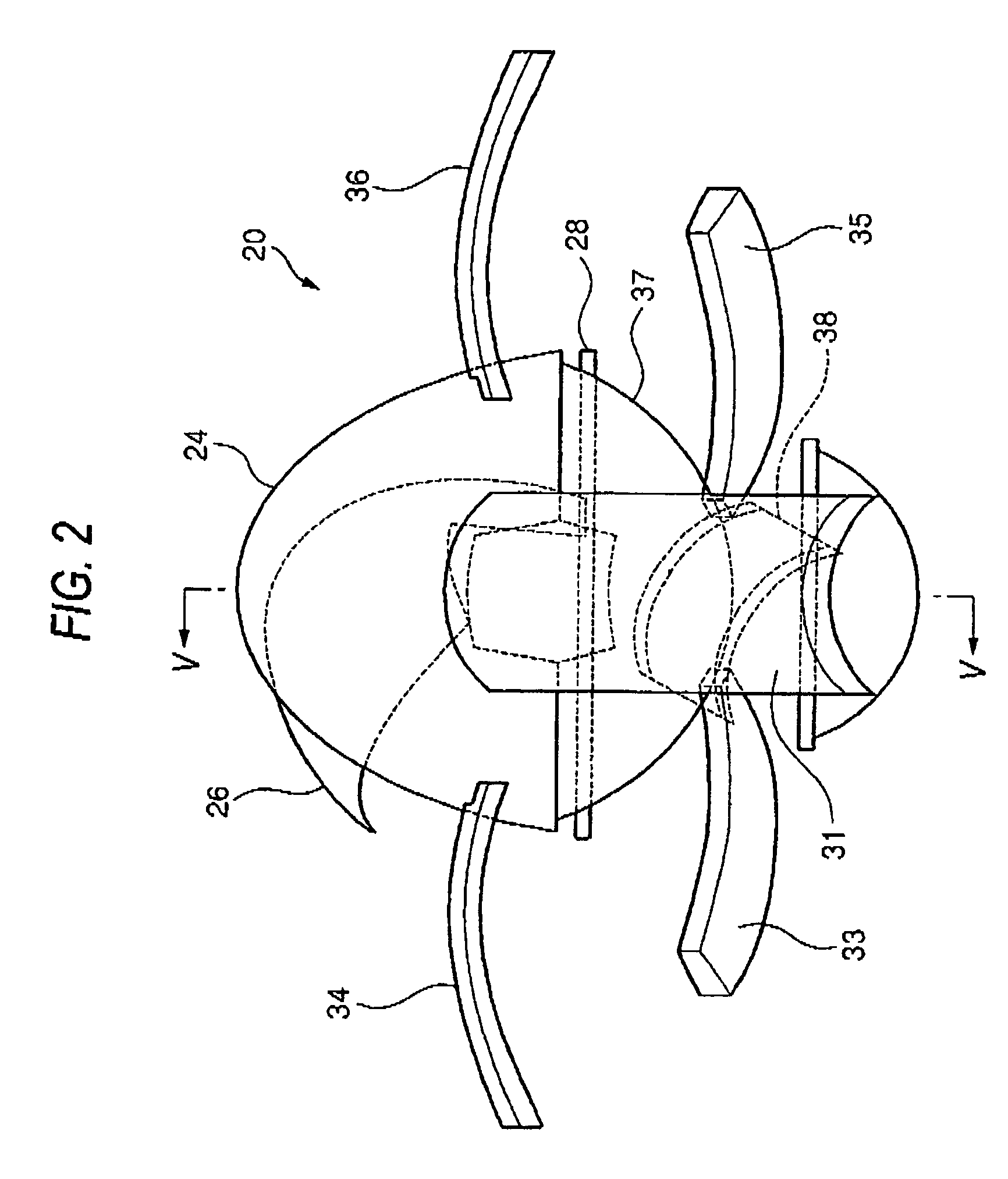
[0030]FIG. 1 is a perspective view of the overall appearance of a vehicle headlamp according to an embodiment of the present invention. FIG. 2 is a top view of the vehicle headlamp according to the embodiment of the present invention. FIG. 3 is a front view of the vehicle headlamp according to the embodiment of the present invention. FIG. 4 is a side view of the vehicle headlamp according to the embodiment of the present invention. FIG. 5 is a sectional view taken in line V-V in FIG. 2. FIG. 6 is a sectional view taken in line VI-VI in FIG. 3. FIG. 7 is a front view of the shade attached to the vehicle headlamp according to the embodiment of the present invention. Incidentally, in FIGS. 1 to 4, the shape of unseen members hidden by the members on the forward side are indicated in broken line.

[0031]A vehicle headlamp 10 according to this embodiment is arranged as a lamp unit 20 within a l...


PUM


Abstract

A vehicle headlamp, for projecting light forward along an optical axis extending in a longitudinal direction of the vehicle, is provided with a light source, a first main reflector, a second main reflector, a shade, and a projection lens. The light source emits light. The first main reflector is arranged above the light source and reflects the light emitted from the light source toward the optical axis. The second main reflector is arranged below the light source and reflects the light emitted from the light source toward a direction different from the optical axis. The shade cuts a part of the light reflected by the first main reflector to form a cut-of line. The projection lens is arranged in front of the first main reflector and forward projects the light having passed the shade.

Description

[0001]The present application claims foreign priority based on Japanese Patent Application No. P.2004-342742, filed on Nov. 26, 2004, the contents of which are incorporated herein by reference.BACKGROUND OF THE INVENTION[0002]1. Field of the Invention[0003]The present invention relates to a large quantity of light type headlamp for use in a vehicle.[0004]2. Related Art[0005]There is a vehicle headlamp for projecting light ahead of the vehicle using a projector type of lamp unit.[0006]Such a projector type of lamp unit serves to forward collect / reflect the light emitted from a light source, arranged in the vicinity on an optical axis extending in a longitudinal direction of the vehicle, toward the optical axis by a reflector, and project the reflected light ahead of the lamp unit through a projection lens arranged in front of the reflector. When a distributed light pattern having a cut-off line on the upper end is formed using this lamp unit, a shade is arranged in the vicinity of th...

Claims


Application Information

Patent Timeline
Patent Type & Authority Patents(United States)
IPC IPC(8): F21V7/00F21Y101/00
CPCF21S48/1388F21S41/255F21S41/321F21S41/323F21S41/43F21S41/365F21S41/172
Inventor TAKADA, KENICHI
Owner KOITO MFG CO LTD
Learn More