Press action simulator for aerial cam set up

a technology of aerial cams and simulators, which is applied in the direction of forging presses, forging/pressing/hammering apparatuses, and tools for forming tools. it can solve the problems of inflating the cost of setting up the press, wasting time and time, and unable to adjust the tools on the slide at the trial and error method, etc., and achieves the effect of quick and accurate operation

Inactive Publication Date: 2008-03-04
ANCHOR LAMINA AMERICA INC
View PDF8 Cites 3 Cited by
  • Summary
  • Abstract
  • Description
  • Claims
  • Application Information

AI Technical Summary

Benefits of technology

[0007]My solution to this long standing problem is to open the press, thereby removing the upper die or shoe from the die work area, and then detach the tool holder, or slide, from the cam adapter and mount the slide directly on the driver. Then move the tool holder on the driver as though it was being moved by the cam adapter, thereby replicating its movement when the press is closed and opened. This movement of the tool holder replicates the movement of the slide which occurs as the cam adapter, slide and driver interact during descent and rise of the cam adapter during normal operation of the press. This replication of tool holder movement does not necessarily correspond exactly to the distance of travel of the tool holder movement during operation of the press, but is sufficient to enable adjustment of the tool or tools on the tool holder in relation to the workpiece. Thus, the slide may be moved in a direction to shift the tools carried thereby and the position of the tools relative to the workpiece can be observed, measured and adjusted because there is no obstruction by the upper die or cam adapter. Thus proper adjustment of the tools on the slide may be carried out quickly and accurately as opposed to the prior trial and error method of adjusting the tools.

Problems solved by technology

The problem is to effect the necessary adjustment despite the obstruction of the die work area by the press dies.
This trial and error method of adjusting the tools on the slide could take many hours of time by several tool and die operators and inflate the cost of setting up the press.

Method used


Image

  • Press action simulator for aerial cam set up
  • Press action simulator for aerial cam set up
  • Press action simulator for aerial cam set up

Examples


Embodiment Construction

)

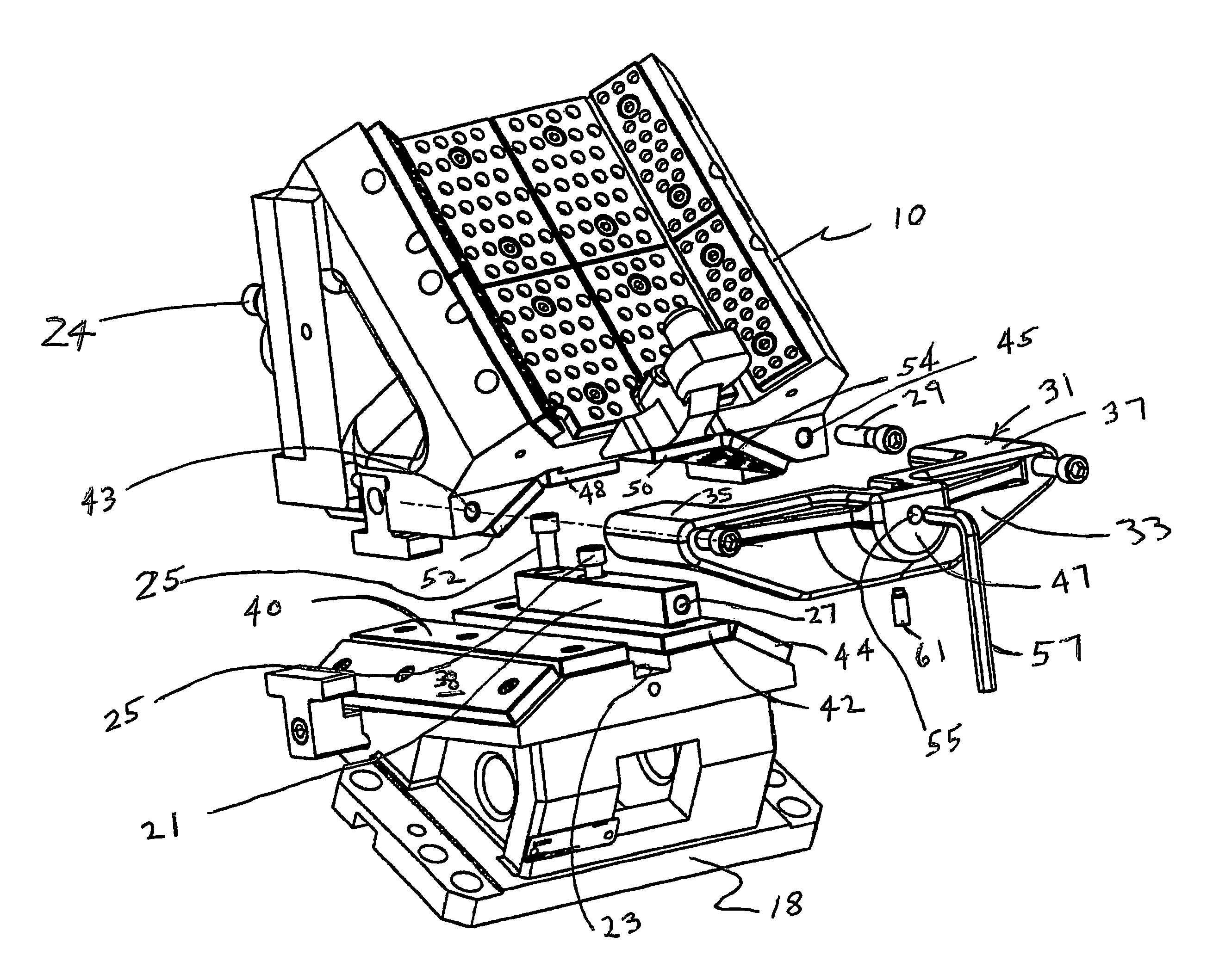
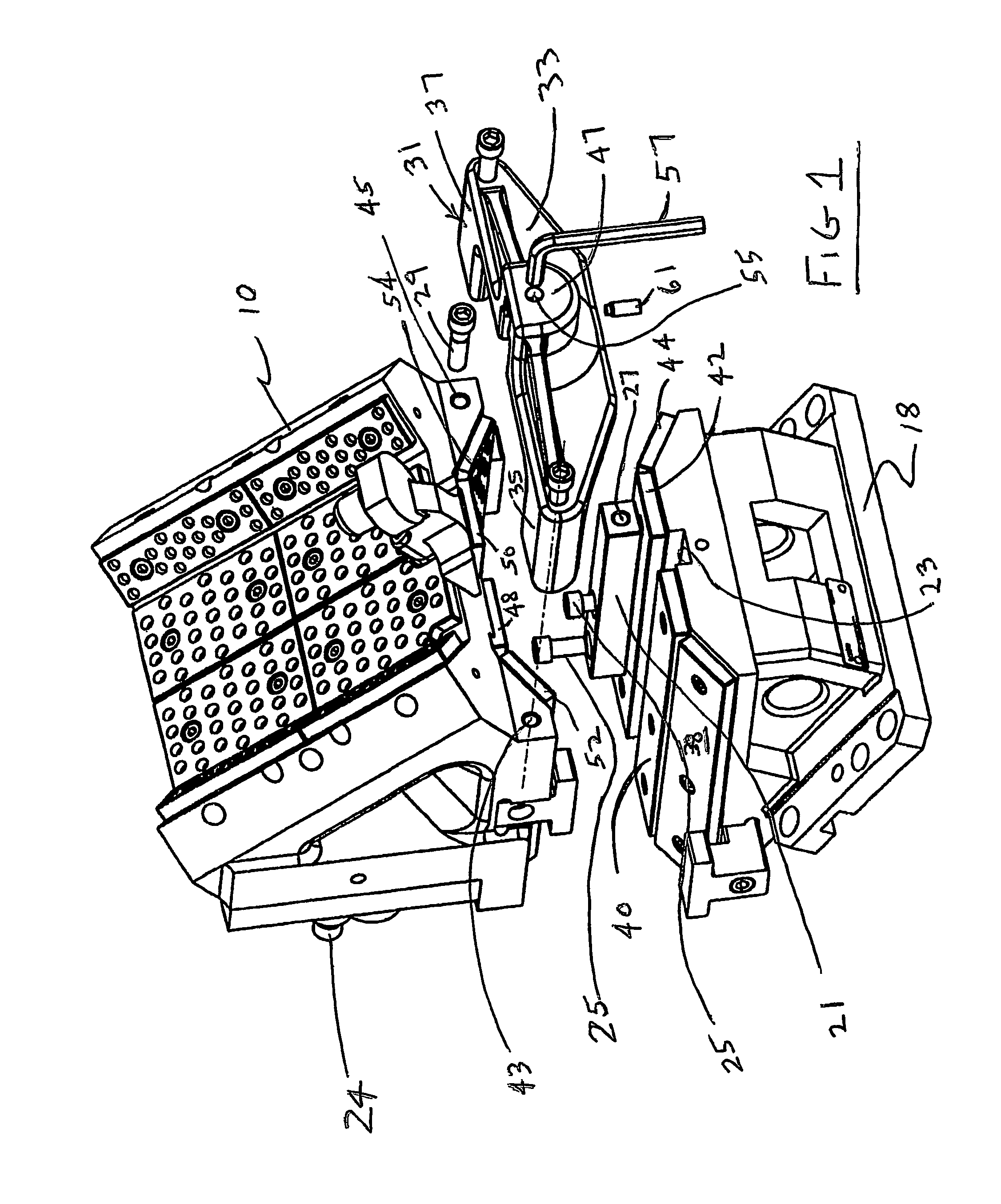
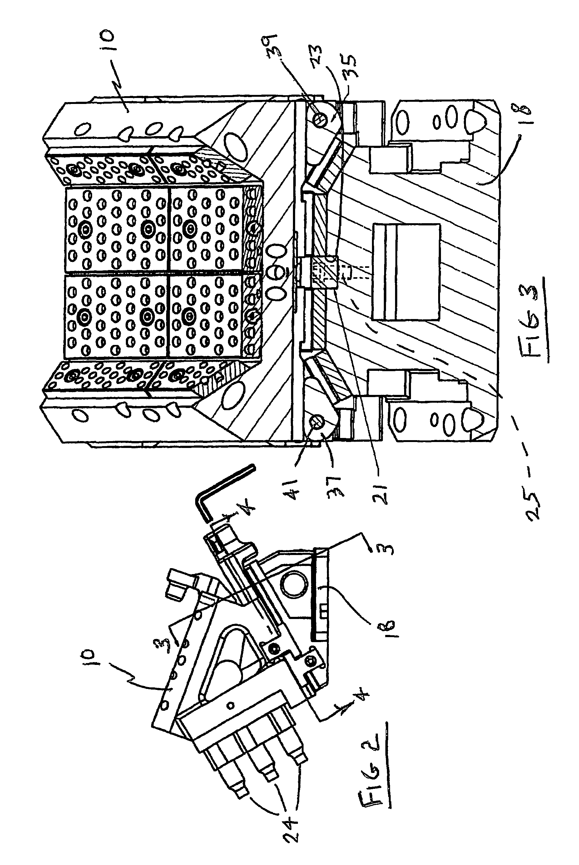
[0016]In U.S. Pat. No. 5,884,521, incorporated herein by reference, and hereinafter the —521 patent, an aerial cam is shown in FIGS. 1 and 2 attached to and between the upper shoe or platen 14 of a sheet metal stamping press, and the lower shoe or platen 20. For clarity of illustration the main forming dies of the press are not shown. A portion of the workpiece, WP, is shown on a workpiece holder WPH, and a tool 24 in FIG. 3 of such patent moves against and retracts away from the workpiece upon, respectively, the descent and the rise of the upper shoe 14 of the press. A cam adapter 12 is fastened to the upper shoe to move therewith. Suspended from the cam adapter 12 is a tool holder 10 on which the tool or tools 24 are mounted which cooperate with the workpiece WP. When the press closes, the upper shoe descends and carries the tool holder 10 downwardly until the holder encounters the driver 18, whereupon the tool holder is shifted laterally (in relation to the path of movement of t...


PUM

PropertyMeasurementUnit
areaaaaaaaaaaa
anglesaaaaaaaaaa
timeaaaaaaaaaa

Abstract

Adjustment of the tools (24) on the tool holder (10) in an Aerial Cam of a metal stamping press may be readily effected by opening the press to remove the upper die (14) from the stamping area and then removing the tool holder (10) on the driver (18) for controlled reciprocation simulating normal operation of the press. The tools (24) may then be adjusted in relation to the workpiece without the interference of the press dies (14 and 20).

Description

BACKGROUND OF THE INVENTION[0001]1. Field of the Invention[0002]This invention relates to the set up of aerial cams in presses for forming sheet metal.[0003]2. Background Art[0004]Aerial cams such as shown in U.S. Pat. Nos. 5,884,521; 5,487,296; 5,101,705 and 5,231,907 have been used for several years in sheet metal stamping operations to facilitate what might be termed secondary operations such as piercing holes, or the deformation of the metal panel (the workpiece) in a fashion that could not be performed by the action of the main dies in the press. The tools which perform such secondary operations are mounted on what is termed a slide, or tool holder, suspended from a cam adapter which is mounted on the upper shoe of the die set. As the upper shoe descends, the slide is carried downwardly and against a driver fastened to the lower die shoe of the press. The angles between the contacting faces of the slide, cam adapter and driver are such that the tool holder is shifted laterally ...

Claims


Application Information

Patent Timeline
Patent Type & Authority Patents(United States)
IPC IPC(8): B21J13/02B21D37/08B21D5/04B21D28/32B21D37/14
CPCB21D5/04B21D28/32B21D37/142
Inventor FIDZIUKIEWICZ, ERICH D.
Owner ANCHOR LAMINA AMERICA INC
Why Eureka
Try Eureka