Fuel system with leak location diagnostic features and component for same

a technology of leak location and fuel system, which is applied in the direction of fluid tightness measurement, instruments, machines/engines, etc., can solve the problems of rare leakage in these types of fuel systems, difficulty in diagnosing leak location in order to repair the same, and inability to detect leakage,

Active Publication Date: 2008-03-04
CATERPILLAR INC
View PDF7 Cites 21 Cited by
  • Summary
  • Abstract
  • Description
  • Claims
  • Application Information

AI Technical Summary

Problems solved by technology

Although leakage in these types of fuel systems is rare, it does occur.
In addition to containing leaks, there is an issue relating to detecting leaks.
Although Wakeman and others have taught methods of detecting a fuel leak in a high pressure common rail system, the problem of diagnosing a leak location in order to repair the same can remain elusive and problematic.
In other words, detecting a leak is useful, but detection alone will not aid a technician in locating and repairing the leak.
Thus, substantial down time and the associated expense can be involved in tracking down and repairing a leak.
This can be further compounded in some engine applications where the various high pressure spaces in the fuel system are at different locations that are difficult to access.

Method used


Image

  • Fuel system with leak location diagnostic features and component for same
  • Fuel system with leak location diagnostic features and component for same
  • Fuel system with leak location diagnostic features and component for same

Examples


Embodiment Construction

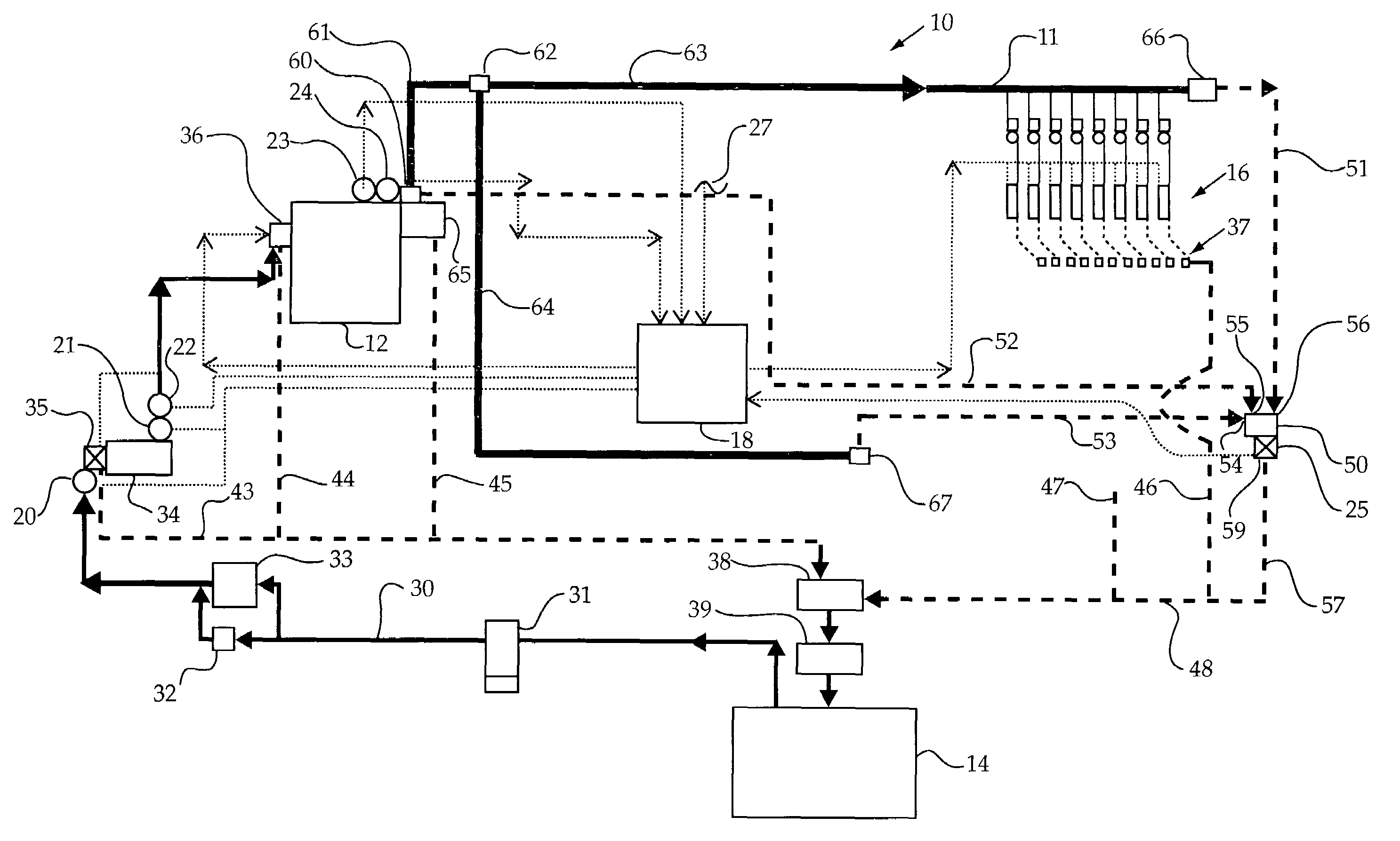
[0016]Referring to FIG. 1, an example fuel system 10 according to the present invention includes a right hand high pressure common rail 11 with eight associated fuel injectors 16, and a left hand common rail (not shown) associated with eight other fuel injectors (also not shown). Fuel system 10 is used in relation to a 16 cylinder V-type diesel engine, and the left hand rail is not shown, but is identical to the right hand rail and associated fuel injectors. Although the present invention is illustrated in association with a common rail fuel system for a V-type diesel engine, the present invention could find potential application to virtually any fuel system that includes, or could be divided into, a plurality of high pressure spaces. Fuel system 10 includes a high pressure pump 12 that supplies high pressure fuel to right hand common rail 11 and the left hand common rail. Low pressure fuel is supplied to high pressure pump 12 from a fuel tank 14. An electronic control module 18 con...


PUM


Abstract

A leak diagnostic strategy for an engine equipped with a high pressure common rail fuel system includes a plurality of separate leak lines. Each of the leak lines is constructed and positioned to capture fuel leaking from one of several different high pressure spaces associated with the fuel system. Once a leak is detected, the location of the leak can be diagnosed by opening different leak diagnostic ports until fuel is evacuated from the system. Each of the leak diagnostic ports is associated with one of the leak lines. The system allows for quick determination of a leak location without cumbersome testing or partial dismantlement of engine related subsystems and components.

Description

TECHNICAL FIELD [0001]The present invention relates generally to a strategy for diagnosing a leak location in a high pressure fuel system, and more particularly to a common rail fuel system with leak location diagnostic features.BACKGROUND [0002]Common rail fuel systems typically include at least one common rail that supplies high pressure fuel to a plurality of fuel injectors, and at least one high pressure pump that supplies high pressure fuel to the common rail(s). These high pressure spaces in an engine's fuel system are fluidly connected to one another through pipes that are located on the engine. Although leakage in these types of fuel systems is rare, it does occur. In order to contain any leak from the high pressure spaces, it is sometimes useful to contain these high pressure spaces within a low pressure envelope. For instance, a high pressure supply line might actually be a double walled tube with the inner tube containing high pressure fuel, and the outer tube enclosing t...

Claims


Application Information

Patent Timeline
Patent Type & Authority Patents(United States)
IPC IPC(8): G01M3/04G01M3/16F02M55/00F02M63/02F02M65/00
CPCF02M55/002F02M63/0225F02M65/00
Inventor SHAMINE, DAVID M.
Owner CATERPILLAR INC
Why Eureka
Try Eureka