
Conference link between a speakerphone and a video conference unit

a conference link and video conference technology, applied in the field of conference equipment including a video conference unit and a speakerphone, can solve the problems of duplicate equipment for each conference unit, video signals are more complicated and bandwidth-intensive than audio signals, and the conference unit is not usually used well with each other

Active Publication Date: 2008-03-04
HEWLETT PACKARD DEV CO LP
View PDF10 Cites 70 Cited by
  • Summary
  • Abstract
  • Description
  • Claims
  • Application Information

AI Technical Summary

Benefits of technology

The present invention is about using a conference link between a video conferencing unit and a speakerphone. This link allows for the transmission of audio signals between the two units. This invention can eliminate redundant equipment in the video conferencing unit and allows for the best audio processing algorithm to be used. The conference link can connect multiple video conference units and speakerphones in serial or parallel. Other data can also be transmitted through the conference link. The invention also includes a dialing program that can adapt the dialing stream with the locations of the near end and the dialed far end. The dialing program can automatically select a mutually supported network or protocol to establish a connection between two sites. Overall, this invention improves the efficiency and effectiveness of video conferencing and collaboration.

Problems solved by technology

Video signals are more complicated and bandwidth demanding than audio signals.
Although video conferencing units and speakerphones have many overlapping features and functionalities, they do not usually work very well with each other.
As a consequence, there is duplicate equipment for each conference unit.

Method used


Image

  • Conference link between a speakerphone and a video conference unit
  • Conference link between a speakerphone and a video conference unit
  • Conference link between a speakerphone and a video conference unit

Examples


Embodiment Construction

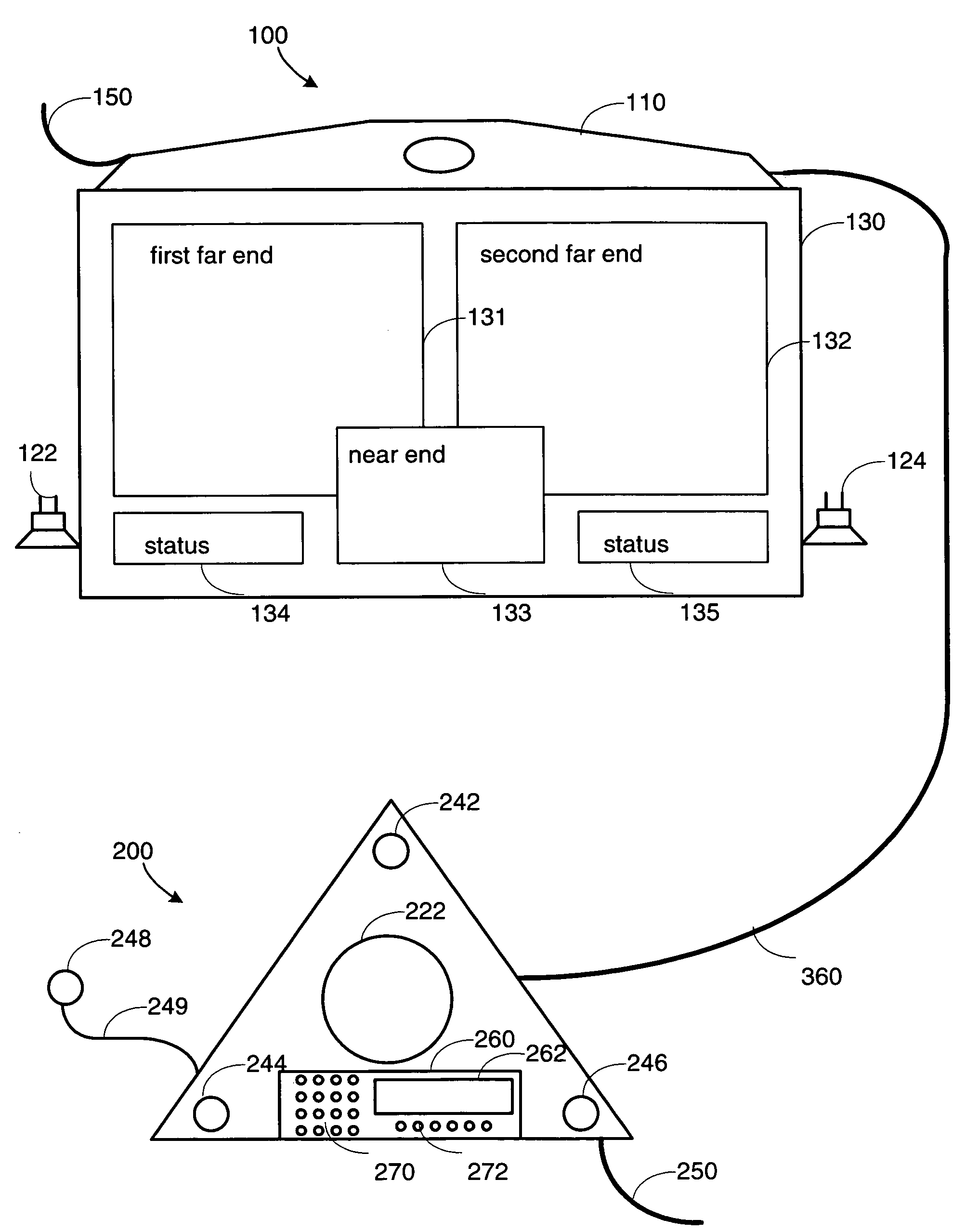
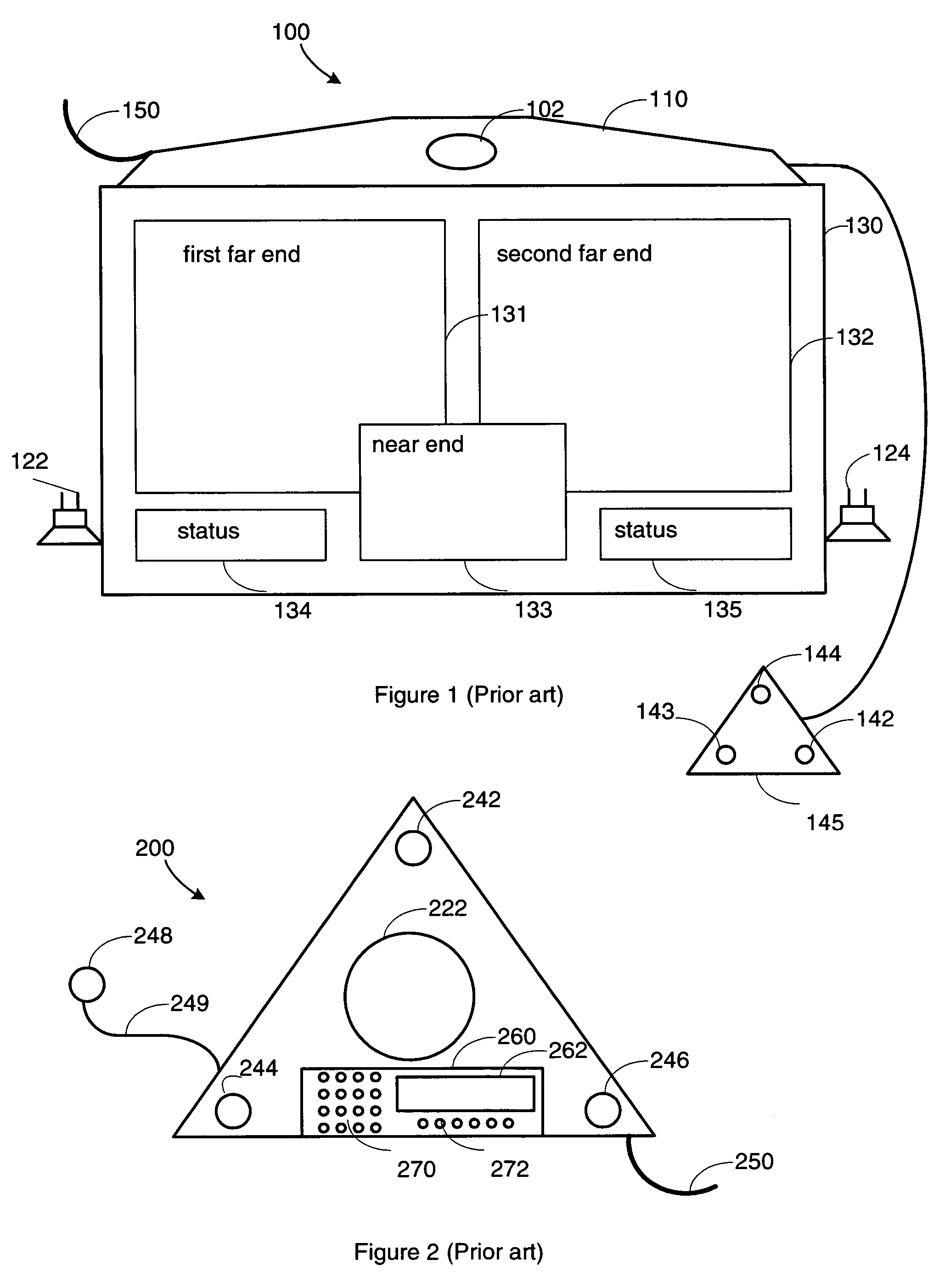
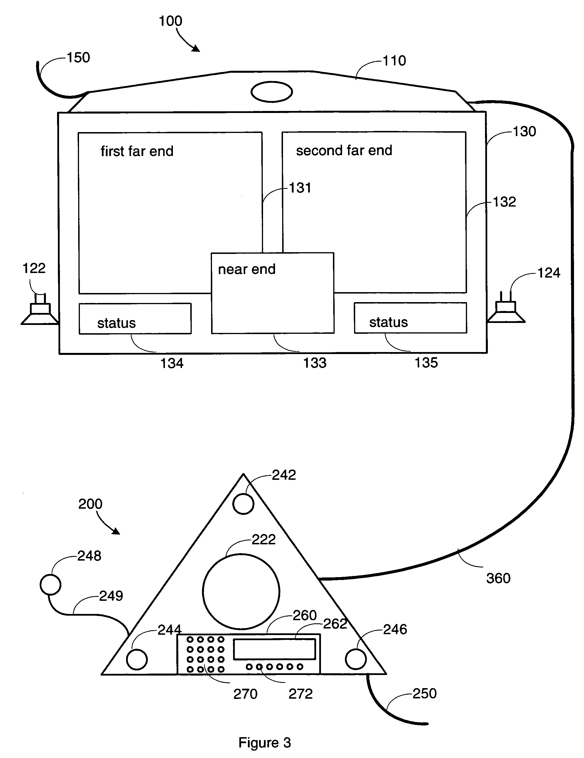
[0024]FIG. 1 illustrates a typical video conferencing unit 100 with a video conferencing module 110 and a display screen 130. In this example, the video conferencing module 110 includes a video camera 102. A microphone pod 145 which contains three microphones 142, 143 and 144 is connected to the module 110. There are many other components inside the video conferencing module 110. A block diagram of a video conference module 110 according to an embodiment of the current invention is shown in FIG. 4. The video conferencing module 110 is connected to a network through cable 150. There are many wires not shown in FIG. 1 that connect the video conferencing module 110 to various networks, including telephone networks or data networks, and to a power supply. The display screen 130 may be a regular TV set or a stand alone video monitor including loudspeakers 122 and 124. Depending on the number of sites of the videoconferencing, the display screen 130 may be divided into smaller windows, su...


PUM


Abstract

A conference link between devices in teleconference system at one site is disclosed. The linked devices include video conference units, speakerphones or stand-alone loudspeakers. Audio data can be transmitted through the conference link between devices. Audio data processing can be performed in either a video conference unit or a speakerphone. The microphones and loudspeakers in the video conference unit may be eliminated. The microphones and loudspeakers in the speakerphone are used. Other data, for example directories of dialing information, may also be transmitted through the conference link and the data processing may be allocated among processors in devices connected by conference links. The conference link may be wired or wireless, analog or digital. The devices may be linked by conference link in parallel or series. A dialing program can adapt the dialing stream with the locations of the near end site and the dialed far end site. The dialing program can automatically select a mutually supported network or protocol to establish a connection between two sites.

Description

CROSS-REFERENCE TO RELATED APPLICATIONS[0001]The current invention is related to a provisional patent application: “A Speakerphone with a Cellular Phone Connection,” by Jeff Rodman and Greg Goldfarb, Ser. No. 60 / 562,782, filed on Apr. 16, 2004 assigned to the same assignee.[0002]This patent application is related to another patent application by Jed Wilson, Kate Nogarede and Greg Rousch, assigned to the same assignee, titled “Method and Apparatus for Videoconference Interaction with Bluetooth-enabled Cellular Telephone.”BACKGROUND OF THE INVENTION[0003]1. Field of the Invention[0004]This invention relates to conference equipment including a video conference unit and a speakerphone, more specifically to enhance and expand the features and functions of a combination of existing and future videoconference units and speakerphones.[0005]2. Description of the Related Art[0006]Teleconferencing has long been an essential tool for communication in business, government and educational institu...

Claims


Application Information

Patent Timeline
Patent Type & Authority Patents(United States)
IPC IPC(8): H04N7/14H04R1/02H04B1/38H04B1/40H04M1/00H04M1/60H04M9/00H04M9/08
CPCH04B1/40H04M1/6033H04M1/6041H04N7/15
Inventor RODMAN, JEFFREYDRELL, DAVIDVANDER KAM, RICK A.SEXTON, MARTIN G.BINFORD, DONNIMRI, ALAINRATCLIFF, JEFFKILDAY, CAROLYNHESS, MICHAEL J.
Owner HEWLETT PACKARD DEV CO LP
Learn More