Manufacturing method for electrooptic device, electrooptic device, and electronic device

Active Publication Date: 2008-03-04
BOE TECH GRP CO LTD
View PDF11 Cites 31 Cited by
  • Summary
  • Abstract
  • Description
  • Claims
  • Application Information

AI Technical Summary

Benefits of technology

[0030]According to the present invention, since the opening in the colored layer has a two-dimensional shape crossing the pixel, it is possible to form the opening into a two-dimensional shape having no corner in the portions other than the boundary region, (i.e., within the pixel), or it is possible to form the opening into a shape such as not to generate the concentration of diffracted light, side etching, or the like in the pixel during a patterning operation. This allows fluctuations in the opening shape in the opening to be inhibited, and enables variations in the opening area thereof to be suppressed, thereby improving the color reproducibility of the reflective display.
[0031]In the present invention, it is preferable that the opening have a two-dimensional shape having no corner in the portions other than the boundary region between the pixels. This further improves the reproducibility of the opening area. Here, the opening is preferably formed into a band shape crossing the pixel.
[0032]In the present invention, it is pre

Problems solved by technology

The transmissive liquid crystal display provides a relatively bright display, but its illumination means such as a backlight requires large power consumption.
This raises a problem in that, when the transmissive liquid crystal display is used for a portable electronic device such as a mobile phone, its operating time is short since the battery capacity is limited.
Another problem with the transmissive liquid crystal is that its display is difficult to view while outdoors during the daytime.
On the other hand, the reflective liquid crystal display requires no illumination means, but the reflective liquid crystal display does not always provide sufficient brightness for display because it makes use of external light.
Therefore, the reflective liquid crystal display particularly involves a problem in that it is deficient in color reproducibility for color display and viewability in

Method used


Image

  • Manufacturing method for electrooptic device, electrooptic device, and electronic device
  • Manufacturing method for electrooptic device, electrooptic device, and electronic device
  • Manufacturing method for electrooptic device, electrooptic device, and electronic device

Examples


first embodiment

[0075]FIG. 4 illustrates the two-dimensional shapes of colored layers 214 in respective pixels in a first embodiment according to the present invention. In the first embodiment, colored layers 214r, 214g, and 214b, respectively, are formed in a plurality of pixels of R, G, and B. An opening 214ra is formed in the colored layer 214r provided for the R (red) pixel, and an opening 214ga is formed in the colored layer 214g provided for the G (green) pixel. No opening is formed in the colored layer 214b provided for the B (blue) pixel. With these arrangements, a part of the reflecting section 212b of the transflective layer 212 that is two-dimensionally superimposed on the colored layer 214r is not covered with the colored layer 214r, but is in an exposed state. Also, parts of the reflecting section 212b of the transflective layer 212 that is two-dimensionally superimposed on the colored layer 214g is not covered with the colored layer 214g, but are in exposed states.

[0076]The above-desc...

second embodiment

[0081]Next, a second embodiment will be described with reference to FIG. 6. In the second embodiment, an opening 414a having a polygonal two-dimensional shape is provided in a colored layer 414 in a pixel. More specifically, the opening 414a is formed by using a mask pattern P4 having an octagonal two-dimensional shape that is formed by chamfering four corners of a rectangular shape. Here, the mask pattern P4 has eight corners, and the interior angle θ of each of these corners is an angle larger than 90 degrees (i.e., an obtuse angle). Particularly in order to effectively reduce variations in the opening shape and opening area, it is preferable that every interior angle be not less than 110 degrees.

[0082]In this way, using the polygonal mask pattern P4 in which the interior angle θ of each of the corners thereof is an obtuse angle makes it possible to inhibit fluctuations in the opening shape and opening area and increase the reproducibility thereof, as compared with the conventiona...

third embodiment

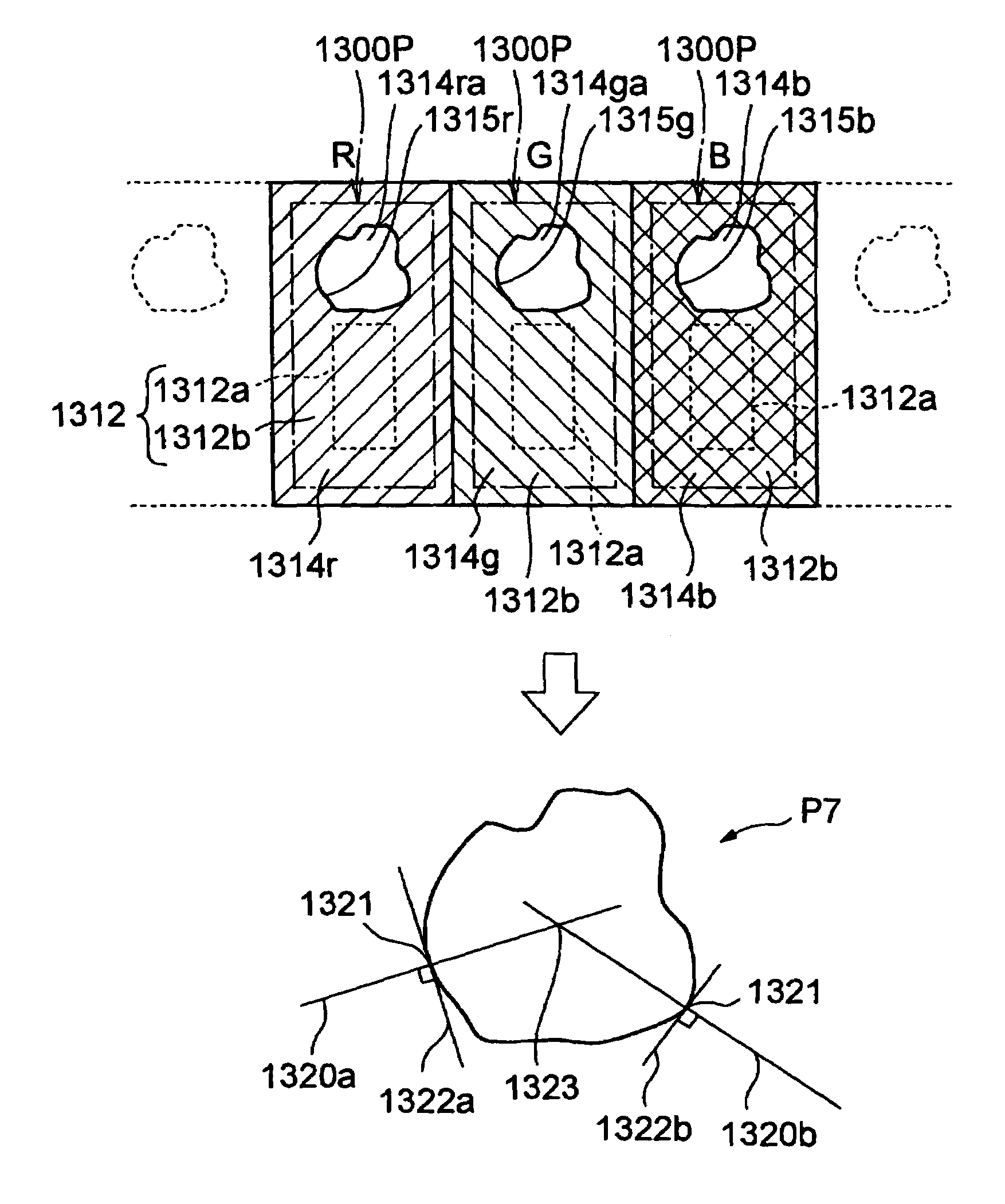
[0087]Next, a third embodiment according to the present invention will be described with reference to FIG. 8. In the third embodiment, an opening 614ra is formed in a colored layer 614r, an opening 614ga is formed in a colored layer 614g, and an opening 614ba is formed in a colored layer 614b. Each of the 614ra, 614ga, and 614ba is configured to cross a pixel 600P. Specifically, each of the openings 614ra, 614ga, and 614ba is arranged to extend from a portion on the boundary line of the pixel 600P and arrive at another portion of the boundary line. In the illustrated example, pixels each having a substantially square two-dimensional shape are formed, and each of the pixels 600P has four side edges. In this embodiment, each case has an opening formed so as to cross at least two different side edges of the pixel 600P. Therefore, not only the case where the opening crosses the pixel 600P in the right-and-left direction (in FIG. 8) as the illustrated example, but also the case where the...


PUM


Abstract

A transflective electrooptic device is provided with an opening formed in a colored layer provided on the reflecting section of a transflective layer. The opening has an elliptical two-dimensional shape, and can be formed, in a patterning process, by a mask pattern having a two-dimensional shape without any corners, such as an elliptical shape. Such an opening makes it possible to inhibit fluctuations in the opening shape and opening area during a patterning operation with respect to the colored layer, and reduces variations in the opening area, thereby increasing the color reproducibility of the reflective display.

Description

BACKGROUND OF THE INVENTION[0001]1. Technical Field[0002]The present invention relates to a manufacturing method for an electrooptic device, an electrooptic device, and an electronic device. More specifically, it relates to a manufacturing method for an electrooptic device having a color filter, and the construction of the same.[0003]2. Related Art[0004]As is known in the art, liquid crystal displays, which are a kind of electrooptic device, generally include a transmissive liquid crystal display, which performs a transmissive display by using transmitted light emitted by illumination means such as a backlight, and a reflective liquid crystal display, which has a reflector plate reflecting external light and which performs a reflective display by using reflected light of the external light. The transmissive liquid crystal display provides a relatively bright display, but its illumination means such as a backlight requires large power consumption. This raises a problem in that, when ...

Claims


Application Information

Patent Timeline
IPC IPC(8): G02F1/1335G02F1/13G02F1/1333G02F1/137
CPCG02F1/133555G02F1/1335
Inventor NAKANO, TOMOYUKITAKIZAWA, KEIJIKANEKO, HIDEKI
Owner BOE TECH GRP CO LTD
Why Eureka
Try Eureka