Piezoelectric anion generator controled by integrated circuit

a technology of integrated circuit and anion generator, which is applied in the direction of electrostatic charge, electrical apparatus, corona discharge, etc., can solve the problems of high failure ratio in use, large volume, and high cost, and achieves small electromagnetic interference, simple insulation, and high step-up ratio

Active Publication Date: 2008-03-04
XIAN KONG HONG NEW MATERIALS SCI TECH +1
View PDF3 Cites 1 Cited by
  • Summary
  • Abstract
  • Description
  • Claims
  • Application Information

AI Technical Summary

Benefits of technology

[0005]In view of the reasons above, an object of the present invention is to provide a piezoelectric anion generator controlled by an integrated circuit IC, which don't require the short-circuit protection and has some advantages such as the high step-up ratio, the simple insulation, the security, the stableness, the small electromagnetic interference and the small volume.
[0016]The present invention has the following advantages from the above description:
[0017]1. In the present invention it is controlled by the integrated circuit IC so that the oscillation circuit and the frequency following-up circuit are simpler, and the frequency modulation is more convenient, and then it can adapt to the changes of the environment temperature better and can work more reliably.
[0018]2. In the present invention the step-up circuit uses the piezoelectric ceramic transformer to generate the AC high voltage and has high step-up ratio, small volume, simple insulation, the security, the stableness and the small electromagnetic interference compared with the traditional wire-wound transformer.
[0019]3. In the present invention it has some advantages such as simple circuit, no short-circuit protection, the security, the stableness and the high reliability, and it can use the batteries to supply the power and is formed to be the portable anion generator.

Problems solved by technology

So it has some shortcomings such as the complex processing technique, the biggish volume, the higher cost, and the high failure ratio in use.
And it sometimes has some catastrophic failures such as the breakdown and the short between the turns in the transformer, and even the burning.

Method used


Image

  • Piezoelectric anion generator controled by integrated circuit
  • Piezoelectric anion generator controled by integrated circuit
  • Piezoelectric anion generator controled by integrated circuit

Examples


Embodiment Construction

[0023]The figures are the embodiments of the present invention.

[0024]To make the present invention known more clearly, the content of the present invention will be further detailed described accompanying with the figures.

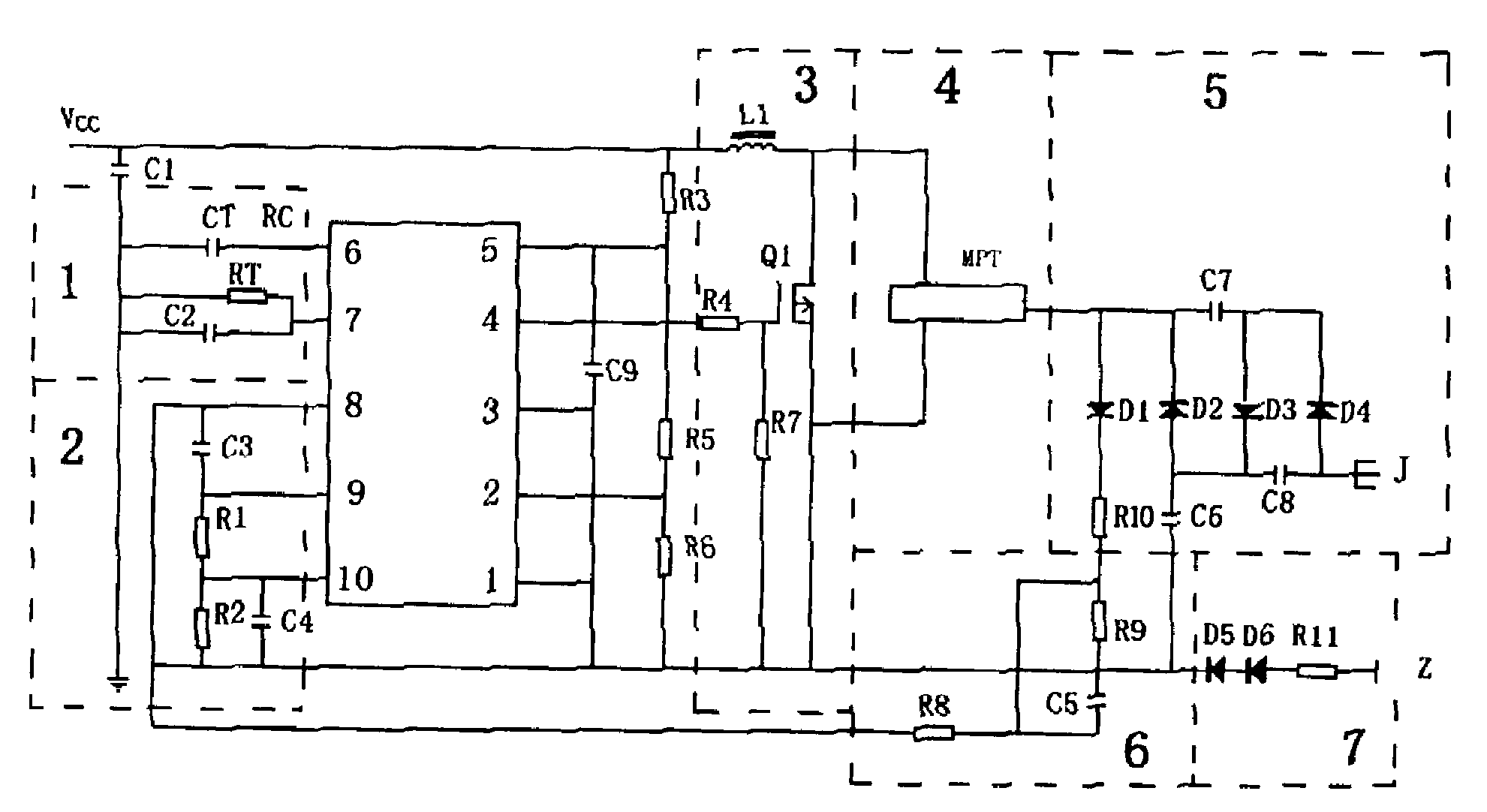
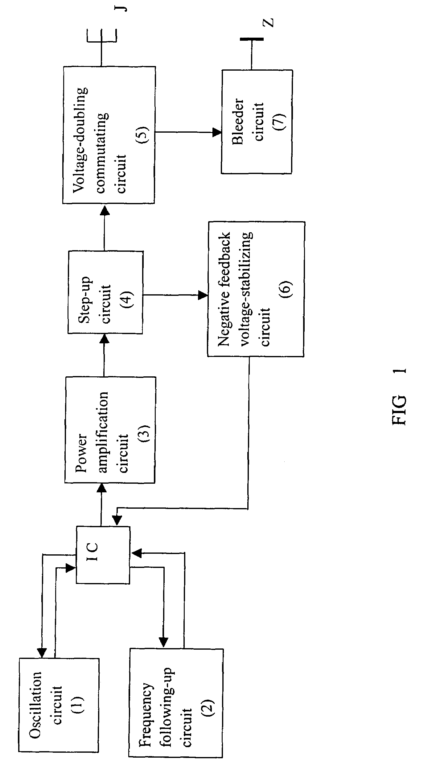
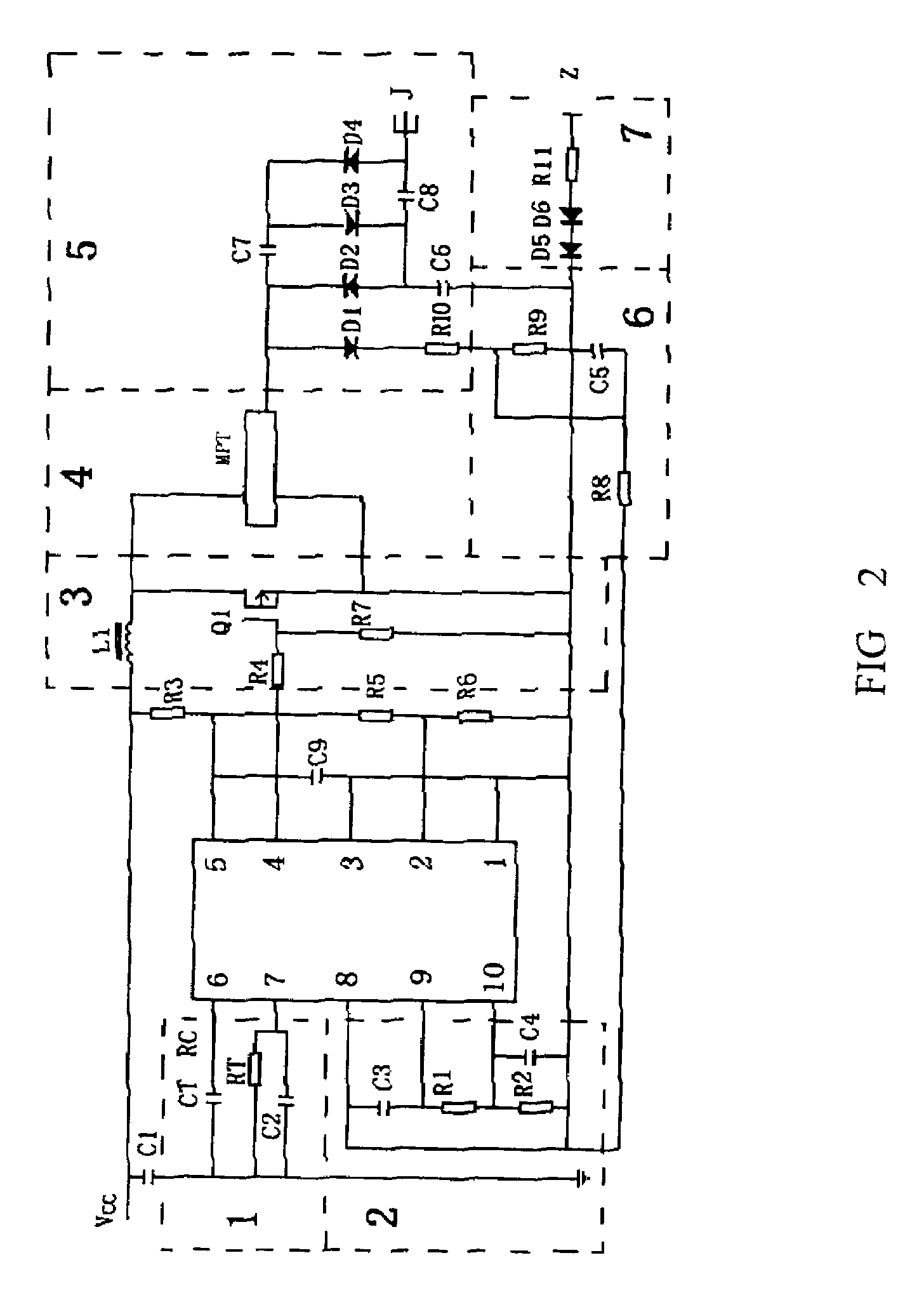
[0025]Referring to FIG. 1, it is mainly composed of seven portions according to the present invention, wherein the integrated circuit IC is connected to the periphery circuit so as to form the oscillation circuit 1, and the integrated circuit IC is connected to the periphery circuit so as to form the frequency following-up circuit 2, and the integrated circuit IC is connected to the power amplification circuit 3, and the power amplification circuit 3 is connected to the step-up circuit 4, and the step-up circuit 4 provides the negative feedback signals and is connected to the integrated circuit IC via the negative feedback voltage-stabilizing circuit 6 and synchronously is connected to the voltage-doubling commutating circuit 5, and the voltage-doubling commutating ...


PUM


Abstract

A piezoelectric anion generator controlled by an integrated circuit IC, which includes an oscillation circuit, a frequency following-up circuit, an power amplification circuit, a step-up circuit, a voltage-doubling circuit, an ion discharging pin, a negative feedback voltage-stabilizing circuit and a bleeder circuit. Due to using the integrated circuit IC controlling circuit, it can provide the AC exciting voltage at the certain frequency to the piezoelectric ceramic transformer and has the functions of regulating the exciting voltage and the frequency following up. The piezoelectric ceramic transformer is used as the main AC step-up element to realize the AC high voltage output. After the voltage-doubling commutation the DC high voltage can be obtained, and the anion-discharging pin connected to it generates the high voltage electrical field, and then the gas is ionized to give out a lot of anions.

Description

BACKGROUND[0001]1. Field of the Invention[0002]The present invention relates to a miniature anion generator in the electric technical field. More particularly, the present invention relates to a piezoelectric anion generator controlled by an integrated circuit IC.[0003]2. Description of Related Art[0004]It is common knowledge that the traditional anion generator usually uses DC / AC converting, and steps up by the wire-wound transformer, and then achieves a needful DC voltage by the voltage-doubling commutating. A discharging pin generates a high voltage electrical field, and then the gas is ionized to give out the anions. It described above requires that the wire-wound transformer have a very high step-up ratio, and it requires that the dielectric strength of the primary winding and the secondary winding of the transformer and the dielectric strength between the turns of the secondary winding are very strong. So it has some shortcomings such as the complex processing technique, the b...

Claims


Application Information

Patent Timeline
Patent Type & Authority Patents(United States)
IPC IPC(8): H01T23/00H01T19/00
CPCH01T23/00
Inventor CHEN, YAOQIANGYANG, ZHEQUAN, PENGHOU, ZHIJUN
Owner XIAN KONG HONG NEW MATERIALS SCI TECH
Why Eureka
Try Eureka