
Patch panels with communications connectors that are rotatable about a vertical axis

a technology of vertical axis rotation and patch panel, which is applied in the direction of electrical apparatus construction details, coupling device connections, instruments, etc., can solve the problems of inability to provide complete bend radius control, difficult to manufacture, and difficult to manage and access

Inactive Publication Date: 2008-03-11
COMMSCOPE INC
View PDF75 Cites 39 Cited by
  • Summary
  • Abstract
  • Description
  • Claims
  • Application Information

AI Technical Summary

Benefits of technology

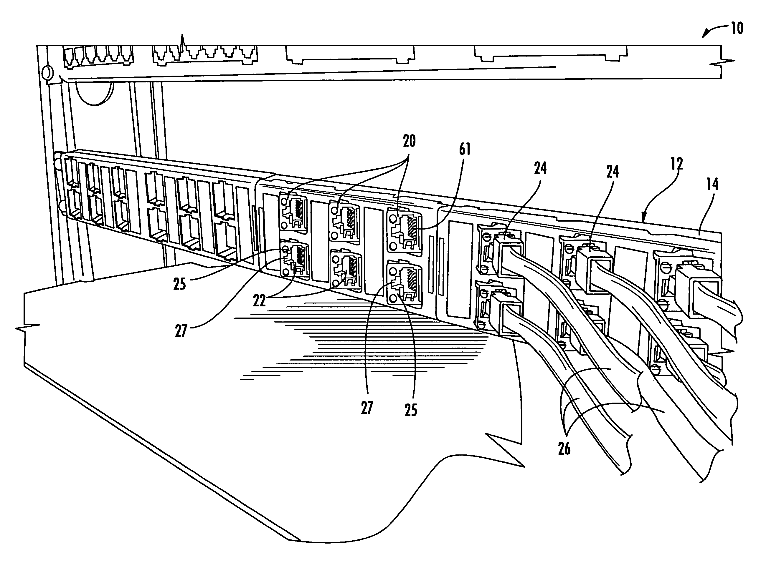
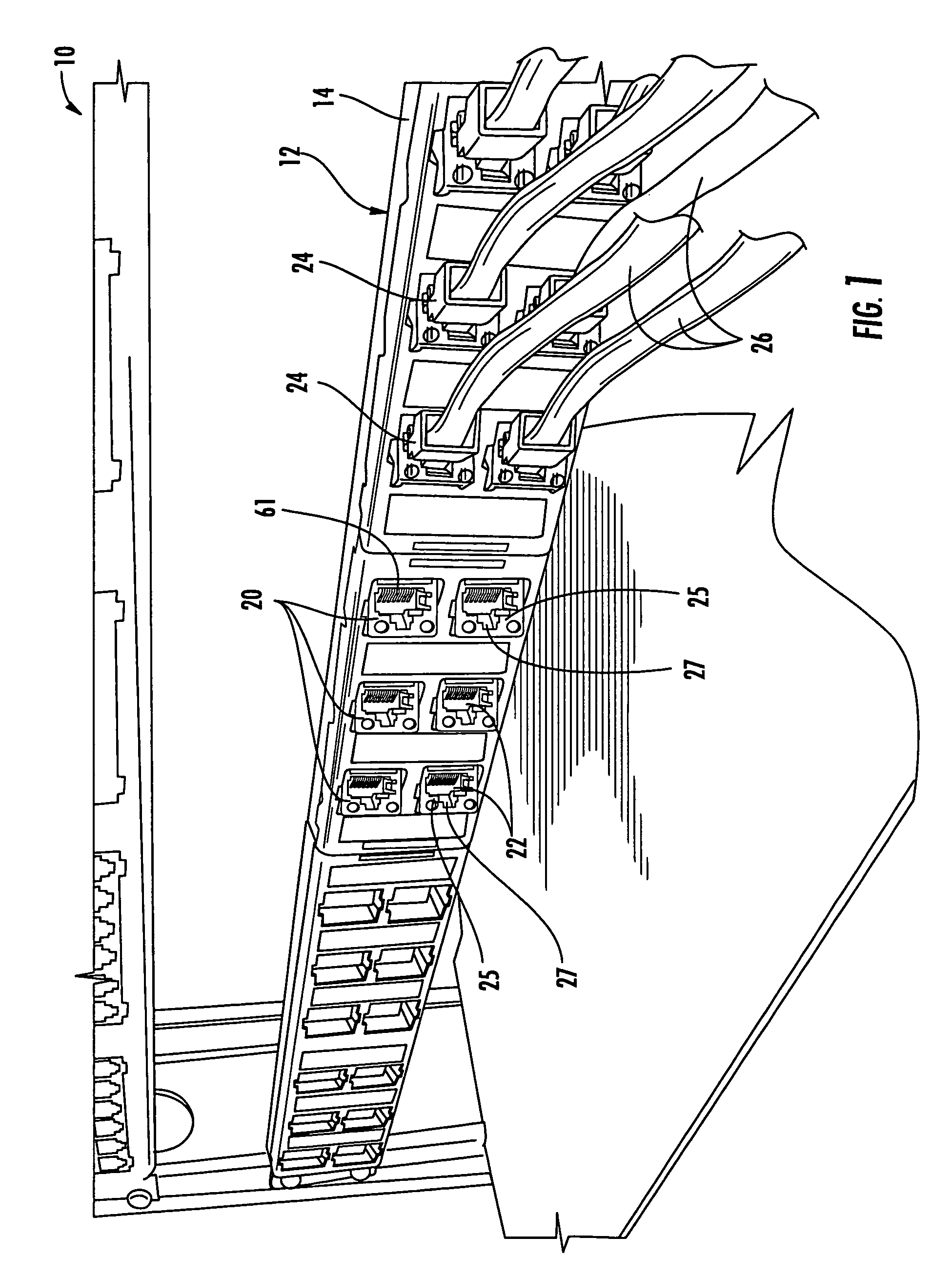
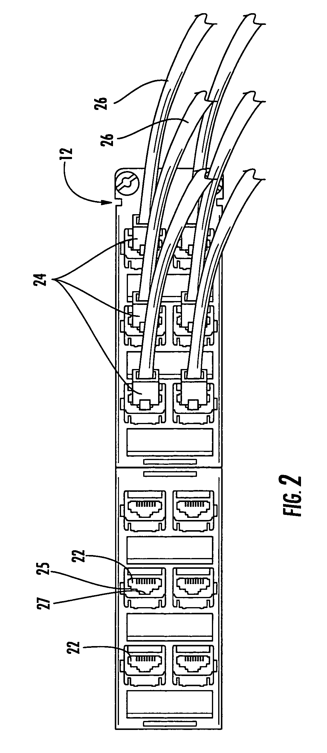
The present invention is directed to a patch panel for mounting to a network rack. The patch panel includes a frame with mounting features, a bezel with outlet apertures, and communication outlets with electrical contacts for receiving mating plugs. The outlets are oriented with a horizontal axis for receiving the mating plug and a plug latch recess. The patch panel can be rotated between a forward-facing orientation and a forward- and laterally-facing orientation within the outlet aperture. The technical effects of the invention include improved mounting and orientation of the patch panel for efficient use of network rack space, and increased flexibility and convenience for users.

Problems solved by technology

Many known systems are unable to provide complete bend radius control, are inefficient, are difficult to manufacture, are difficult to manage and access, and / or have other drawbacks.
One shortcoming of this design is that the extension of the patch panel forwardly of the rack may require additional space.

Method used


Image

  • Patch panels with communications connectors that are rotatable about a vertical axis
  • Patch panels with communications connectors that are rotatable about a vertical axis
  • Patch panels with communications connectors that are rotatable about a vertical axis

Examples


Embodiment Construction

[0019]The present invention will be described more particularly hereinafter with reference to the accompanying drawings. The invention is not intended to be limited to the illustrated embodiments; rather, these embodiments are intended to fully and completely disclose the invention to those skilled in this art. In the drawings, like numbers refer to like elements throughout. Thicknesses and dimensions of some components may be exaggerated for clarity.

[0020]Unless otherwise defined, all terms (including technical and scientific terms) used herein have the same meaning as commonly understood by one of ordinary skill in the art to which this invention belongs. It will be further understood that terms, such as those defined in commonly used dictionaries, should be interpreted as having a meaning that is consistent with their meaning in the context of the relevant art and will not be interpreted in an idealized or overly formal sense unless expressly so defined herein.

[0021]The terminolo...


PUM


Abstract

A patch panel configured for mounting to a network rack, includes: a frame including mounting features at opposite lateral ends for mounting the patch panel to the network rack; a bezel mounted to the patch panel, the bezel including a plurality of outlet apertures, and a plurality of communication outlets mounted in respective ones of the outlet apertures. Each of the outlets includes a plurality of electrical contacts within a plug aperture configured to receive a mating plug. The plug aperture has a generally horizontal axis for receiving the mating plug and further includes a plug latch recess. The outlets are oriented such that the plug latch recess is positioned on one side edge of the plug aperture.

Description

FIELD OF THE INVENTION[0001]The present invention is directed generally to communication connectors, and more specifically to connectors employed with patch panels.BACKGROUND OF THE INVENTION[0002]Communications cables, such as shielded and unshielded twisted pair cables, coaxial cables, and fiber optic cables, transmit data, voice, video and / or audio information in the telecommunications industry. Network equipment enclosure rack systems are well-known in this industry for managing and organizing such cables as they are routed to and from various destinations.[0003]Rack systems typically include a distribution frame rack on which one or more patch panels, network equipment, fiber optic enclosures and the like are mounted. Rack systems serve various functions, including their use as slack trays, splice trays, cable organizers and patch panels. These rack systems also serve as interconnect or cross-connect enclosures when they interface with equipment. Additionally, rack systems may ...

Claims


Application Information

Patent Timeline
Patent Type & Authority Patents(United States)
IPC IPC(8): G02B6/00H01R33/945
CPCH01R9/2408H01R13/518H01R13/743H05K7/186H04Q2213/13003H01R24/62
Inventor SPISANY, GORDONWRIGHT, STANLEYFITZPATRICK, BRIANBOUCINO, THOMAS J.
Owner COMMSCOPE INC
Learn More