Electrocautery surgical scissors

Inactive Publication Date: 2008-03-18
MAQUET CARDIOVASCULAR LLC
View PDF44 Cites 129 Cited by
  • Summary
  • Abstract
  • Description
  • Claims
  • Application Information

AI Technical Summary

Problems solved by technology

However, placement of the electrodes in relation to the tissue-shearing edges of the blades may inhibit proper operation of the blades to

Method used


Image

  • Electrocautery surgical scissors
  • Electrocautery surgical scissors
  • Electrocautery surgical scissors

Examples


Embodiment Construction

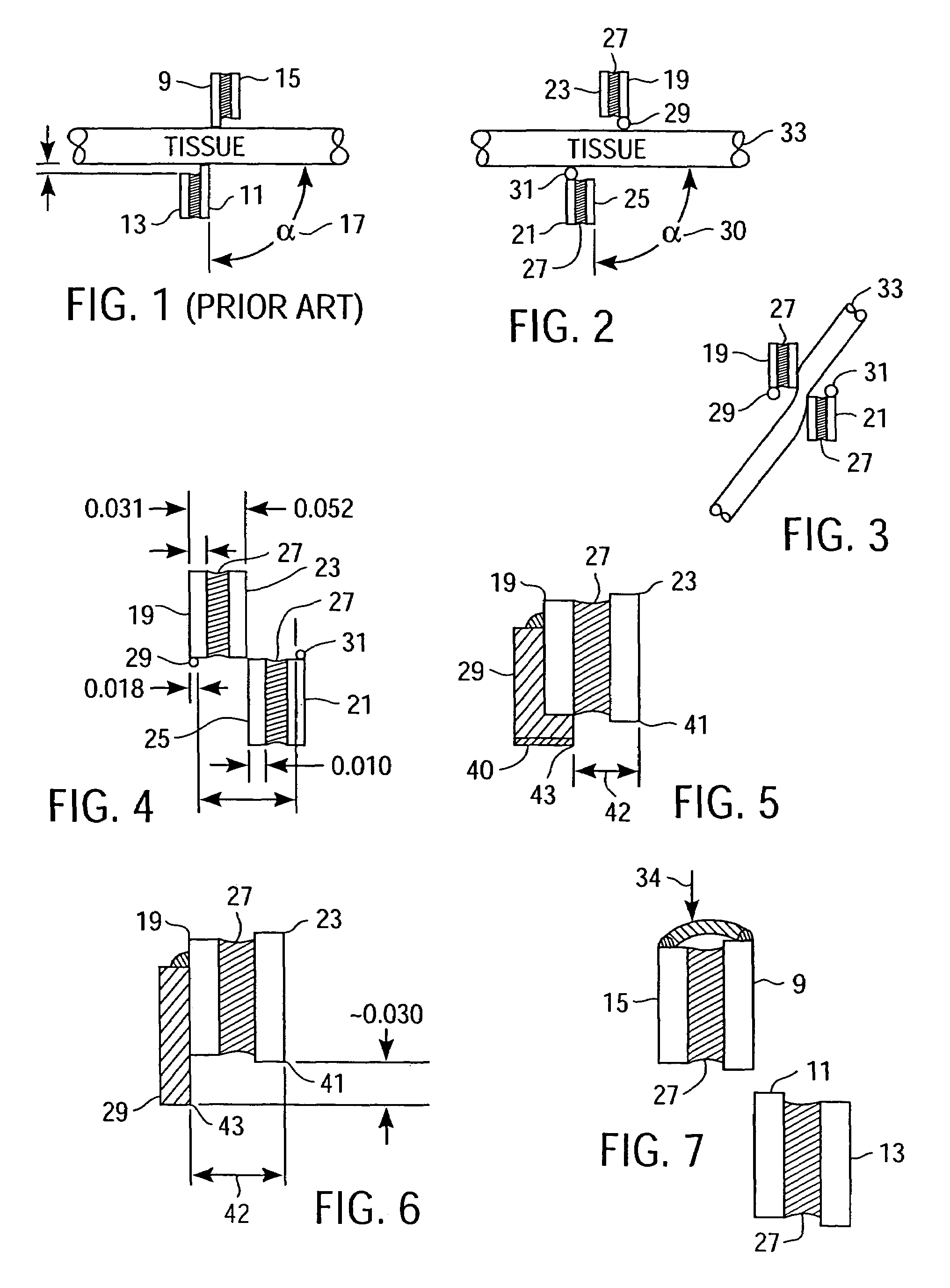
[0015]Referring now to FIG. 1, there is shown a cross-sectional end view of conventional surgical scissors that include both shearing blades 9, 11 and electrically-conductive blade supports 13, 15 that carry in insulated manner the respective cutting blades 9, 11. In this configuration, the cutting blades 9, 11 are positioned against tissue (typically a lateral or side branch vessel of a main vessel such as a saphenous vein) in preparation for cutting the tissue prior to or coincident with contact being made with the tissue by the blade supports serving as electrodes 13, 15. As a result, electrocauterization of the tissue is not possible until either the cutting blades 9, 11 penetrate tissue sufficiently to engage the electrodes 13, 15, or the angle 17 of presentation of the tissue to the cutting blades 9, 11 is skewed sufficiently (by an obtuse angle in the illustration) for the electrodes 13, 15 to contact the tissue prior to contact therewith by the shearing blades 9, 11, or the ...


PUM


Abstract

Surgical apparatus includes bipolar electrodes and tissue-shearing blades configured to electrically contact tissue for electrocauterization thereof prior to shearing contact of the cutting blades with the tissue over wide angles of presentation of the tissue to the electrodes and blades. Extensions or protrusions disposed along facing edges of the electrodes separate the level at which tissue is electrically contacted by the electrodes from the level at which tissue is sheared by the cutting blades.

Description

RELATED APPLICATIONS[0001]This is application is a continuation of application Ser. No. 10 / 071,940, entitled “Electrocautery Surgical Scissors,” filed on Feb. 5, 2002 by J. Lunsford et al., and now issued as U.S. Pat. No. 6,749,609. The subject matter of this application relates to the subject matter described in application Ser. No. 09 / 739,595 entitled “Elongated Surgical Scissors,” filed on Dec. 15, 2000 by T. Chang et al., now issued as U.S. Pat. No. 6,506,207, which subject matter is incorporated herein by this reference.FIELD OF THE INVENTION[0002]This invention relates to surgical instruments incorporating scissors and to surgical scissors, and more particularly to surgical scissors having electrocautery electrodes disposed adjacent tissue-cutting blades for selective cauterization and shearing of tissue.BACKGROUND OF THE INVENTION[0003]Endoscopic surgery commonly requires manual manipulation of surgical instruments that are introduced into a surgical site within a patient thr...

Claims


Application Information

Patent Timeline
IPC IPC(8): A61B18/18A61B18/14
CPCA61B18/1442A61B17/32A61B2018/00595A61B2018/146
Inventor LUNSFORD, JOHN PSTEWART, MICHAEL C
Owner MAQUET CARDIOVASCULAR LLC
Why Eureka
Try Eureka