Motor stator core with skewed slots and production process therefor

a technology of motor stator and slot, which is applied in the direction of magnetic circuit rotating parts, magnetic circuit characterised by magnetic materials, magnetic circuit shape/form/construction, etc., can solve the problems of deterioration of efficiency and difficulty in reducing dimensions, and achieve the effect of suppressing torque fluctuation, preventing torque deterioration, and shortening the bridging portion of a winding

Inactive Publication Date: 2008-03-18
HONDA MOTOR CO LTD
View PDF13 Cites 6 Cited by
  • Summary
  • Abstract
  • Description
  • Claims
  • Application Information

AI Technical Summary

Benefits of technology

[0015]The present invention has been accomplished with the above-mentioned circumstances in mind, and it is an aspect thereof to downsize a stator and prevent deterioration of torque by shortening bridging portions of a winding while suppressing torque fluctuation by skewing slots of the stator.
[0017]Accordingly, since the teeth radially project from the plurality of positions spaced in the peripheral or circumferential direction of the annular stator core, and the plurality of slots are formed between the teeth and skewed, the fluctuation of torque is suppressed, which permits the motor to rotate smoothly. Further, since the winding alternately passes through slots having different skew directions, the reduction in torque due to the skewing of the slots is compensated for by decreasing the length of the bridging portions of the winding, which makes no contribution to the generation of torque, and increasing the length of portions within the slots which contribute to the generation of torque. Furthermore, since the winding is bent at an obtuse angle at opposite ends of the bridging portions, not only does the winding operation for the winding become easy, but the height to which the bridging portions project from the stator core is decreased to reduce the axial dimensions of the stator.
[0020]Since the stator core and the teeth are formed from a compacted powder, the number of components is reduced. Moreover, the number of components can be reduced while increasing the lamination factor of the winding and eliminating the need for insulating paper by rounding the edges at opposite ends of the slots which are in contact with the winding.
[0021]In a first step of the production process, an intermediate steel plate product is formed by pressing a steel plate material using a press die to obtain a first cutout group that is formed at equal intervals in the circumferential direction and from cutouts for half the number of the plurality of slots. In a second step of the process, a final steel plate product is formed by pressing the intermediate steel plate product using the same press die while changing the phase between the press die and the intermediate steel plate product according to the axial position of the final steel plate product in the stator to obtain a second cutout group formed at equal intervals in the circumferential direction and from cutouts for half the number of the plurality of slots in addition to the first cutout group. Therefore, it is possible to produce a large variety of steel plates having different phases between the first cutout group and the second cutout group using a single type of press die, thereby reducing the time and cost required for producing the steel plates.
[0023]Therefore, it is possible to efficiently form a large number of final steel plate products having different phases between the first cutout group and the second cutout group.

Problems solved by technology

However, when short pitch winding or distributed winding is used, as shown in FIG. 12A, in a winding 04 wound around slots 03 between teeth 02 of a stator 01, bridging portions 04a, which do not contribute to the generation of torque, become long, leading to problems.
For example, the winding resistance increases, which results in a deterioration of efficiency.
Also, when opposite ends of the bridging portion 04a are bent through 90°, an axial projection height H of the stator 01 increases, which makes it very difficult to reduce dimensions.

Method used


Image

  • Motor stator core with skewed slots and production process therefor
  • Motor stator core with skewed slots and production process therefor
  • Motor stator core with skewed slots and production process therefor

Examples


second embodiment

[0048]the present invention is now explained with reference to FIG. 8 to FIG. 10.

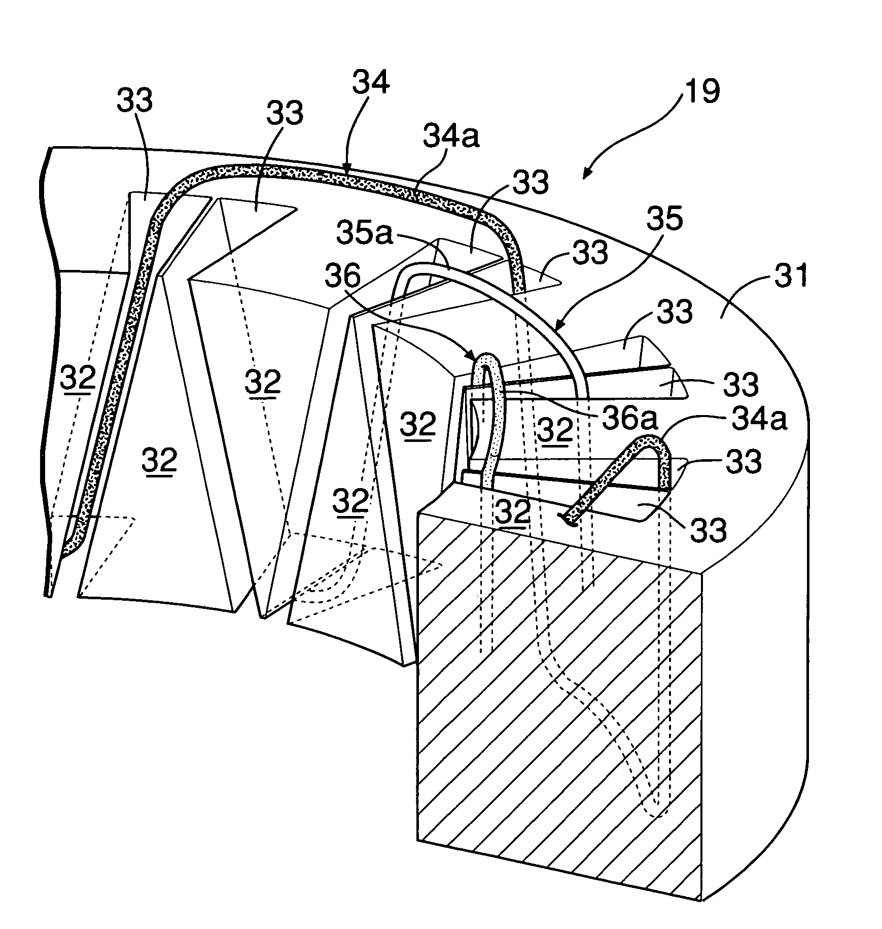
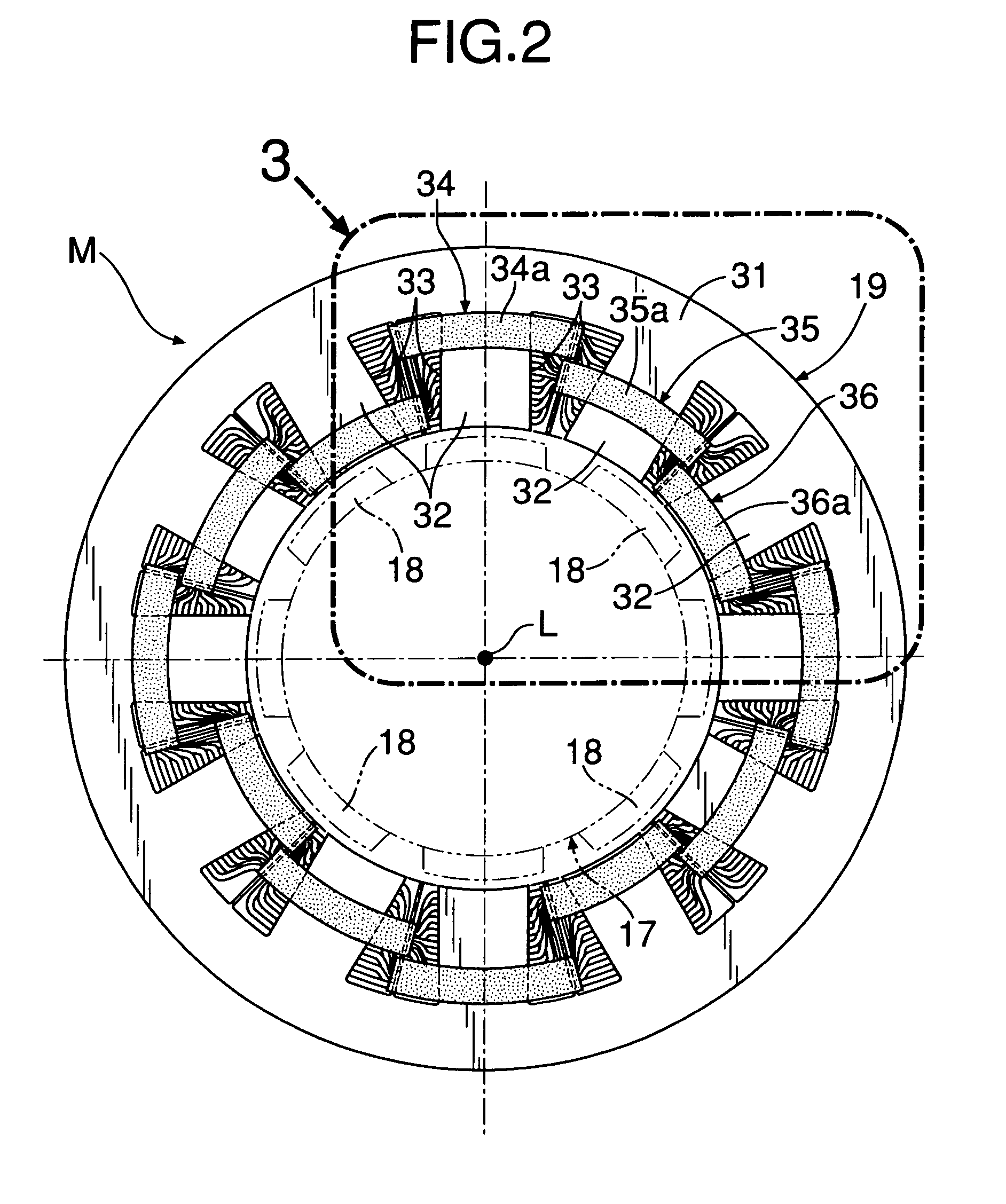
[0049]As is clear from FIG. 8, a stator core 31 and teeth 32 of the second embodiment are formed from a large number of steel plates 32a laminated in an axial direction L of the stator 19. Since the direction of the slots 33 positioned between the teeth 32 is skewed relative to the axial direction L, the shape of the steel plates 32a, forming the stator core 31 and the teeth 32, varies depending on the position in the axial direction L in the stator 19.

[0050]That is, as is clear from FIG. 9, each steel plate 32a includes a first cutout group formed from eight cutouts a and a second cutout group formed from eight cutouts b to correspond to sixteen slots 33. The eight cutouts a, forming the first cutout group, are arranged at equal intervals of 45° in the circumferential direction. The eight cutouts b, forming the second cutout group, are arranged at equal intervals of 45° in the circumferential direction...


PUM


Abstract

In a motor stator, teeth radially project from an annular stator core, and a plurality of slots formed between adjacent teeth are skewed. Phase windings alternately pass through slots having different skew directions, wherein the length of bridging portions, which do not contribute to generation of torque, is short and the length of the portions which are located in the slots, and which contribute to the generation of torque, is long. Further, the phase windings are bent at an obtuse angle at opposite ends of the bridging portions.

Description

RELATED APPLICATION DATA[0001]Japanese priority application Nos. 2004-34982 and 2004-280984, upon which the present application is based, are hereby incorporated in their entirety herein by reference.BACKGROUND OF THE INVENTION[0002]1. Field of the Invention[0003]The present invention relates to a motor stator wherein teeth radially project from a plurality of positions spaced in the peripheral direction of an annular stator core, and wherein a winding is wave-wound around the teeth.[0004]2. Description of the Related Art[0005]In a motor having a stator in which windings having a plurality of phases are wound around slots formed between teeth, short pitch winding and distributed winding are used to suppress the generation of torque ripple or abnormal torque harmonics due to the slots and to obtain smooth rotation. See Japanese Patent Application Laid-open No. 4-721461 and Japanese Patent No. 2765764.[0006]However, when short pitch winding or distributed winding is used, as shown in ...

Claims


Application Information

Patent Timeline
Patent Type & Authority Patents(United States)
IPC IPC(8): H02K1/18H02K3/04H02K3/12H02K1/02H02K1/16H02K3/28H02K15/02
CPCH02K1/165H02K2201/06
Inventor IMAI, NOBUYUKITAKAHASHI, TADANOBUTAJIMA, SHIGERUSEKI, MASAHIROKIKUCHI, HIROYUKIAOKI, SHIN
Owner HONDA MOTOR CO LTD
Why Eureka
Try Eureka