Method and apparatus for improved depth matching of borehole images or core images

a technology of depth matching and boreholes, applied in seismology for waterlogging, instruments, reradiation, etc., can solve the problems of uniform motion, inconvenient use, and inability to accurately match the depth of the borehole,

Inactive Publication Date: 2008-03-18
SCHLUMBERGER TECH CORP
View PDF12 Cites 19 Cited by
  • Summary
  • Abstract
  • Description
  • Claims
  • Application Information

AI Technical Summary

Problems solved by technology

One problem is that the movement downhole of a tool with its sensors is usually not uniform.
The non-uniform motion may be caused by such thing as: (a) damped longitudinal oscillations of the logging tool on the cable, (b) sticking and slipping of the logging tool against the sides of a borehole or the wall of casing in the borehole, and (c) irregular motion of the sensors that are mounted on mechanical arms that have independent motion with respect to the logging tool itself.
As a result of non-uniform motion of the logging tool, data collected by a particular sensor on the logging tool at any specific depth in the borehole may not show as being recorded at the specific depth but at a different depth.
While methods for depth correlating data obtained using sensors spaced vertically from each other on a well logging tool, or obtained at separate times of the same borehole are known, some of these methods are very complex and there is a need for a better method to depth correlate data obtained from well logging tool sensors.

Method used


Image

  • Method and apparatus for improved depth matching of borehole images or core images
  • Method and apparatus for improved depth matching of borehole images or core images
  • Method and apparatus for improved depth matching of borehole images or core images

Examples


first embodiment

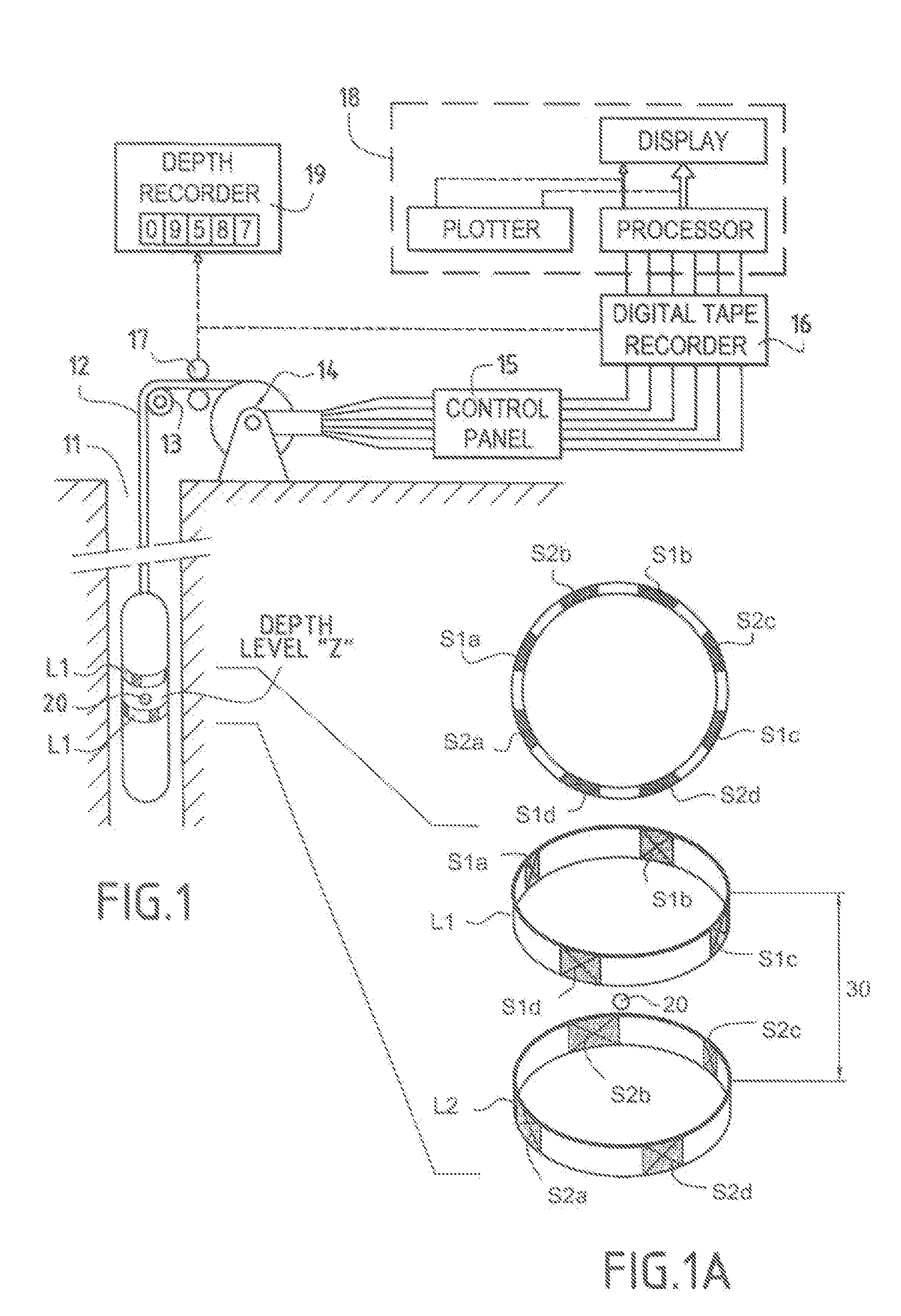
[0025]Briefly, in the present invention, individual traces from the sensors of any first specific level of sensors on a logging tool are converted into one signal representing those traces. The one signal represents all the traces (averaged log signal) and includes an average borehole-crossing signal. The averaged log signal is generated by performing a prior art computation of bedding dips or flowlines (angle and azimuth) on the traces from each sensor and an average or median computation is applied to all the samples from sub-sensors that comprise each sensor aligned along the pre-determined dip. This is repeated for a second specific level of sensors vertically offset from the first specific level of sensors and a second averaged signal is obtained. Then a prior art single log trace depth matching technique is applied to two averaged signals to determine the optimum depth “offset” necessary to precisely match the two averaged signals. The “offset” determined is then applied to th...

second embodiment

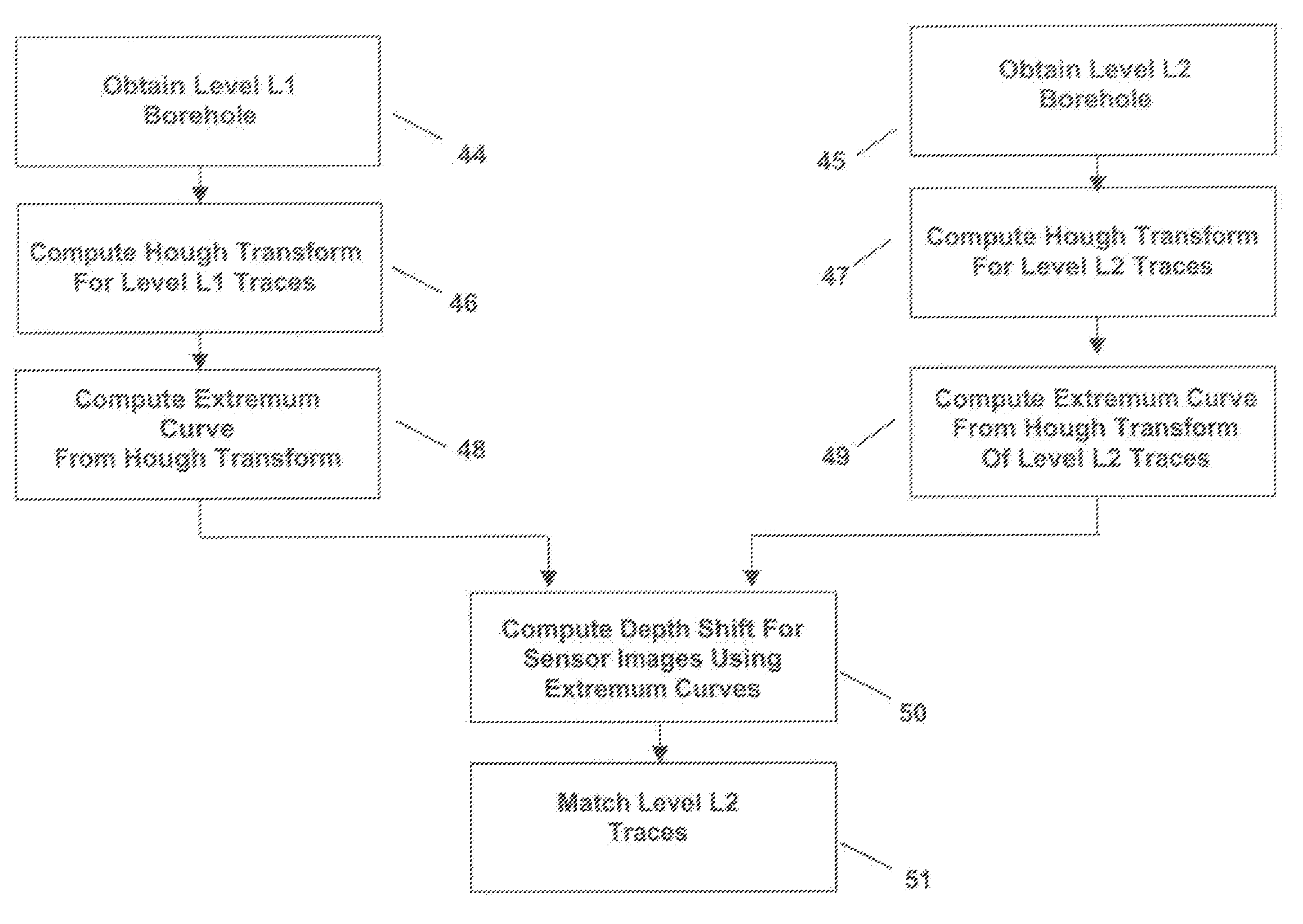
[0026]Briefly, in the present invention the Hough transform is utilized to generate three-dimensional images from well log signals. The three dimensional images are used to create two-dimensional extremum curves that are in turn used to calculate an offset. The offset is used to depth match the well log signals obtained from vertically spaced sensors on a well logging tool, or signals obtained during different logging passes through the same borehole. The detrimental effects of partial and non-overlapping sensor coverage of a borehole wall are reduced, if not eliminated, because of the characteristics of the Hough image transform, and because depth matching is finally applied to the two dimensional extremum curves derived from the three-dimensional images. More specifically, a depth matching offset is calculated directly from two dimensional extremum curves derived from the Hough three-dimensional images without the need for calculating dip and azimuth of bed boundaries in an earth ...


PUM


Abstract

A method for depth matching borehole images and / or core section images is disclosed wherein signals from sensors at different levels on a logging tool are converted into an averaged signal representing the average bed signal at the center of the borehole at each of the different levels. A depth matching technique is applied to the averaged signals from the sensors at different levels on the logging tool to determine the optimum depth offset necessary for matching two sets of signals from sensors at the different levels of the logging tool. In an alternative embodiment of the invention a Hough transform is utilized to process the well log images and generate three-dimensional images in Hough space. The three dimensional images are converted into two-dimensional extremum curves. Depth matching is performed on the two dimensional extremum curves to calculate an offset to match the two dimensional extremum curves. The calculated offset is then applied to the well log images to depth match them.

Description

FIELD OF THE INVENTION[0001]This invention relates to logging of boreholes. More specifically, the invention relates to a method for improving correlation of core images, borehole images and well logging data derived from sensors located on a well logging tool as it passes through a borehole.BACKGROUND OF THE INVENTION[0002]In a typical prior art oil well logging scenario, a string of well logging tools having multiple sensors for measuring characteristics of the earth formation along the wall of a borehole is lowered via a cable to the bottom of the borehole. Geophysical data is recorded by way of the sensors as the cable is wound in using a precision winch. The depth in the earth at which the sensors on the logging tools are positioned as data is logged is determined by measuring the logging speed and cable depth. Devices such as a depth wheel measurement instrument and an axial accelerometer may be utilized.[0003]Typically, measurements taken along the length of a borehole by log...

Claims


Application Information

Patent Timeline
Patent Type & Authority Patents(United States)
IPC IPC(8): G01V1/40G01V1/00G01V3/20G01V3/38
CPCG01V3/20G01V3/38G01V11/00
Inventor MATHIEU, GILLESDELHOMME, JEAN-PIERRECHEUNG, PHILIPWANG, YINYU
Owner SCHLUMBERGER TECH CORP
Why Eureka
Try Eureka