Electrically non-conductive sleeve for use in wellbore instrumentation

a technology of electric non-conductive sleeves and wellbores, applied in instruments, surveying, borehole/well accessories, etc., can solve the problem of heavy housing

Active Publication Date: 2010-03-25
SCHLUMBERGER TECH CORP
View PDF9 Cites 64 Cited by
  • Summary
  • Abstract
  • Description
  • Claims
  • Application Information

AI Technical Summary

Problems solved by technology

However, such housings are heavy, and can be expensive to make.

Method used


Image

  • Electrically non-conductive sleeve for use in wellbore instrumentation
  • Electrically non-conductive sleeve for use in wellbore instrumentation
  • Electrically non-conductive sleeve for use in wellbore instrumentation

Examples


Embodiment Construction

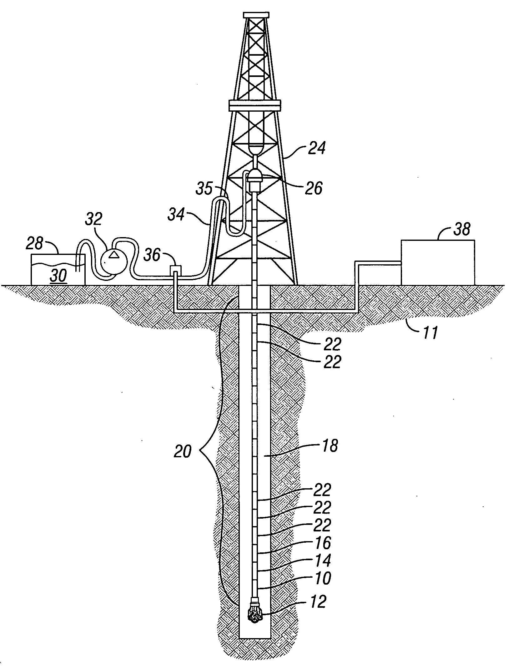
[0020]An example wellbore instrumentation system that may be disposed in a composite tubular housing made according to one example of the invention is shown schematically in FIG. 1. The present example is described in terms of drilling instrumentation, however it should be understood that an instrument housing according to the various aspects of the invention may be used in wellbore instruments that are conveyed along a wellbore using any other known conveyance devices, including without limitation by armored electrical cable (“wireline”), coiled tubing, production tubing, smooth-wire (“slickline”) and wellbore tractor. Therefore, the invention is not limited in scope to housings that are coupled within a drill string

[0021]In FIG. 1, a drilling rig 24 or similar lifting device suspends a conduit called a “drill string 20” within a wellbore 18 being drilled through subsurface rock formations 11. The drill string 20 may be assembled by threadedly coupling together end to end a number ...


PUM


Abstract

A well logging instrument housing includes an electrically non-conductive tube and at least one layer of fiber embedded in a matrix surrounding an exterior of the tube. The at least one fiber layer includes at least one carbon fiber. The at least one or carbon fiber is arranged to have substantially no closed loops.

Description

CROSS-REFERENCE TO RELATED APPLICATIONS[0001]Not applicable.STATEMENT REGARDING FEDERALLY SPONSORED RESEARCH OR DEVELOPMENT[0002]Not applicable.BACKGROUND OF THE INVENTION[0003]1. Field of the Invention[0004]The invention relates generally to the field of measuring instrumentation used in wellbores drilled through subsurface rock formations. More specifically, the invention relates to structures usable as housings for such instrumentation.[0005]2. Background Art[0006]Wellbore-deployed instrumentation includes various sensing devices disposed in a housing or “sub” coupled within a conduit called a “drill string” suspended in a wellbore for the drilling of such wellbore. A drill string is a length of pipe generally assembled from segments (“joints”) threadedly coupled end to end and having a drill bit at the lower end of the drill string. Drilling is performed by rotating and axially urging the drill bit to the bottom of the wellbore to extend the length of the wellbore. Wellbore depl...

Claims


Application Information

Patent Timeline
Patent Type & Authority Applications(United States)
IPC IPC(8): F16L11/00G01V3/18F16L9/12
CPCG01V3/18E21B47/01
Inventor HOMAN, DEAN M.
Owner SCHLUMBERGER TECH CORP
Why Eureka
Try Eureka