
Carbon Fiber Reinforced Peek Bone Plate With Titanium Fixation Screws

a technology of titanium fixation and carbon fiber, which is applied in the field of carbon fiber reinforced peek bone plate with titanium fixation screw, can solve the problems of difficult to compute the correct amount of bone to remove, non-union between the upper and lower bones, and several extra cuts

Active Publication Date: 2010-01-21
ARTHREX
View PDF20 Cites 110 Cited by
  • Summary
  • Abstract
  • Description
  • Claims
  • Application Information

AI Technical Summary

Benefits of technology

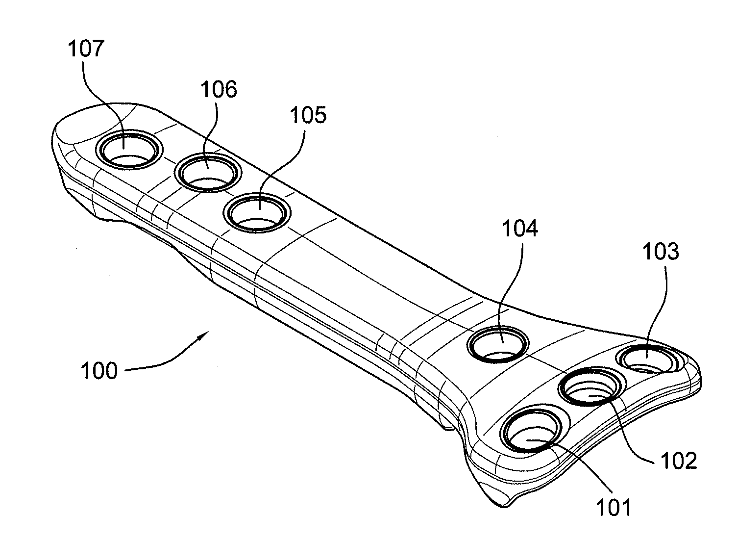
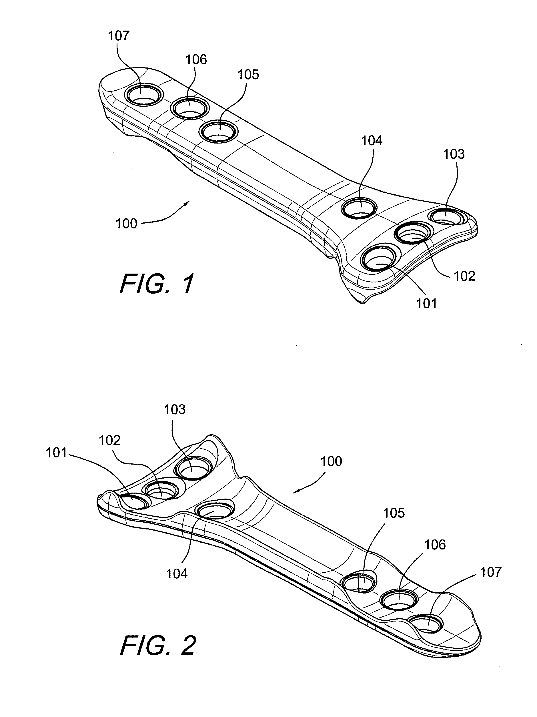
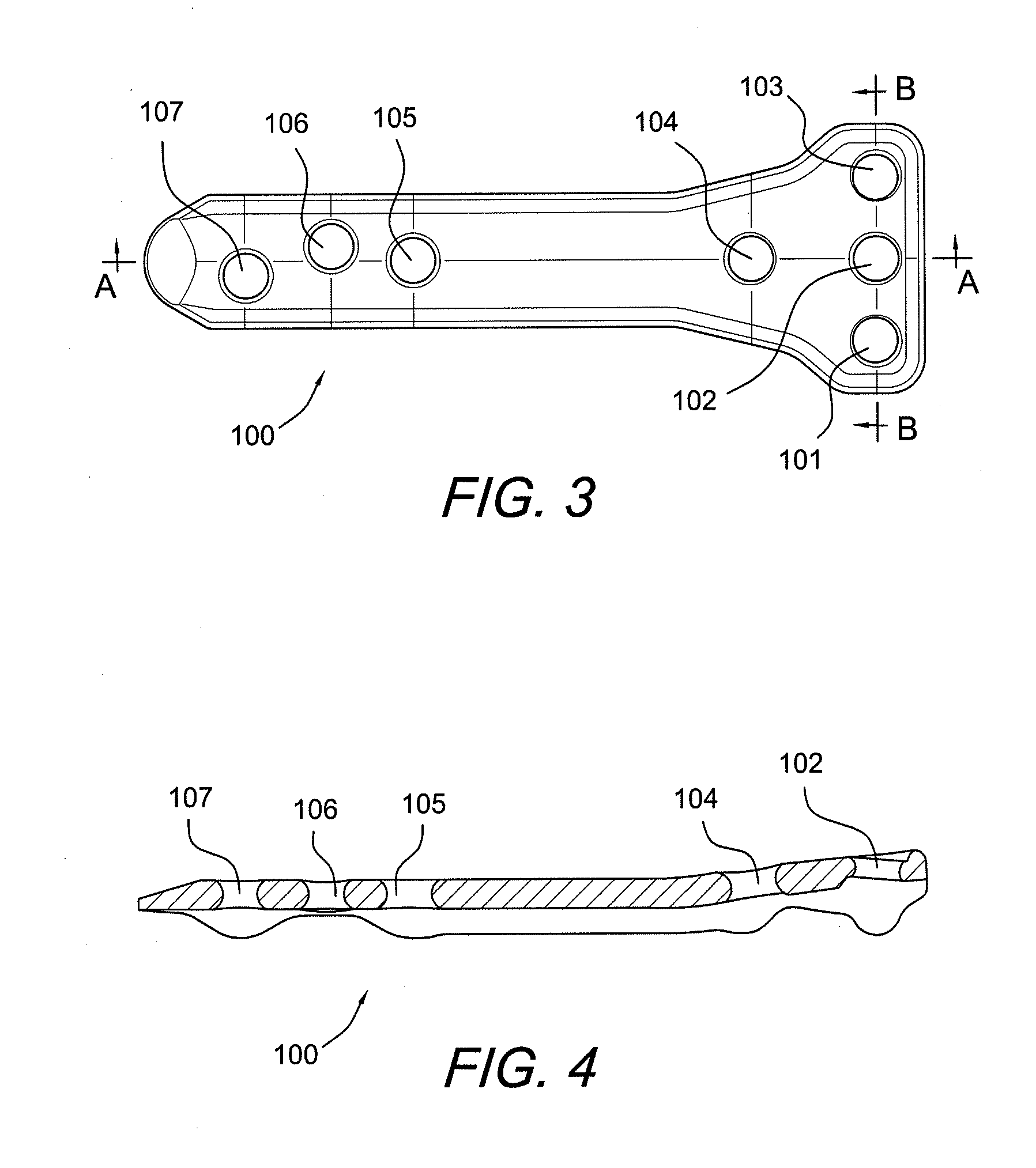
[0010]The bone plate is formed of a material softer than the material of the fixation devices, and is provided with fixation apertures or holes with rounded, curved interior walls (i.e., non-threaded holes) that allow the fixation devices to be inserted at various angles. The fixation apertures or holes have a diameter smaller than that of the fixation devices. As a result of the differences between the materials of the plate and of fixation devices, and between the diameters of the fixation holes and of the fixation devices, the fixation devices deform the interior walls of the fixation holes, therefore “self-threading” the holes at an advantageous angle. The “self-threading” of the fixation holes of the plate by the fixation devices eliminates the need for prior threading or tapering of the fixation holes.

Problems solved by technology

The closed wedge method is the current standard, although several disadvantages are associated with this technique.
The most significant disadvantages of the closed wedge method are: (1) disruption of the tibial-femoral joint; (2) possible damage to neurovascular structures; and (3) disruption of the medial cortex, resulting in instability and nonunion between the upper and lower bone because of possible soft tissue interference.
It is also difficult to compute the correct amount of bone to remove and, therefore, several extra cuts may be required.
This is disadvantageous because it may prevent a surgeon from adjusting the insertion angle of the fixation screws to better accommodate the curvature of a patient's bone.

Method used


Image

  • Carbon Fiber Reinforced Peek Bone Plate With Titanium Fixation Screws
  • Carbon Fiber Reinforced Peek Bone Plate With Titanium Fixation Screws
  • Carbon Fiber Reinforced Peek Bone Plate With Titanium Fixation Screws

Examples


Embodiment Construction

[0034]In the following detailed description, reference is made to various specific embodiments in which the invention may be practiced. These embodiments are described with sufficient detail to enable those skilled in the art to practice the invention, and it is to be understood that other embodiments may be employed, and that structural and logical changes may be made without departing from the spirit or scope of the present invention.

[0035]The present invention provides apparatus and methods for tissue fixation (for example, tissue to bone fixation) using a bone plate configured to accommodate fixation devices (such as screws, for example) inserted at various angles. The bone plate is formed of a material softer than the material of the fixation devices, and is provided with fixation apertures or holes with rounded, curved interior walls (i.e., non-threaded holes) that allow the fixation devices to be inserted at various angles. As a result of the difference between the material o...


PUM


Abstract

Apparatus and methods for tissue fixation using a bone plate configured to accommodate fixation devices (such as screws, for example) inserted at various angles. The bone plate is formed of a material softer than the material of the fixation devices, and is provided with fixation holes with rounded, curved interior walls (i.e., non-threaded holes) that allow the fixation devices to be inserted at various angles. The fixation holes have a diameter smaller than that of the fixation devices. As a result of the difference between the materials of the plate and of fixation devices, and of the difference between the diameters of the fixation holes and of the fixation devices, the fixation devices deform the interior walls of the fixation holes, therefore self-threading the holes at an advantageous angle.

Description

CROSS-REFERENCE TO RELATED APPLICATIONS[0001]This application claims the benefit of U.S. Provisional Application No. 61 / 082,408, filed Jul. 21, 2008, the entire disclosure of which is incorporated by reference herein.FIELD OF THE INVENTION[0002]The present invention relates to a carbon fiber reinforced PEEK bone plate with titanium fixation screws, and to a method for performing high tibial open wedge osteotomy using the bone plate.BACKGROUND OF THE INVENTION[0003]Treatment of pain or instability associated with lower extremity misalignment may require surgical interventions, such as osteotomy. High tibial osteotomies are indicated by early, medial joint-space narrowing, by early arthritis in patients who have had previous medial meniscectomy, or following rupture of the anterior cruciate ligament in patients with pre-existing varus deformity, for example.[0004]Two osteotomy methods are known in the art: the closed wedge method, and the open wedge method. In the closed wedge method,...

Claims


Application Information

Patent Timeline
IPC IPC(8): A61B17/80
CPCA61B17/1728A61B17/8057A61B17/8605A61B17/1764A61B2017/0256A61B17/8095A61B17/8635A61B17/8061
Inventor MICHEL, GERLINDE
Owner ARTHREX
Learn More