Golf club head

a golf club and head technology, applied in the field of golf club head, can solve the problems of limiting the maximum value of the restitution coefficient of the head, and achieve the effects of reducing the amount of backspin of the ball, reducing the angle of hitting the ball, and small deformation of the center portion

Active Publication Date: 2007-10-09
SUMITOMO RUBBER IND LTD
View PDF29 Cites 26 Cited by
  • Summary
  • Abstract
  • Description
  • Claims
  • Application Information

AI Technical Summary

Benefits of technology

[0008]The present invention is worked out while taking the problems mentioned above into consideration, and a main object of the present invention is to provide a golf club head which serves for improving a carry of a hit ball, by optimizing an angle of hitting the ball and an amount of backspin.
[0010]In the golf club head in accordance with the present invention, the thickness of the peripheral portion of the face portion is reduced from the sole portion of the head toward the crown portion side. Accordingly, when hitting the ball by the center portion, the crown portion side of the peripheral portion is largely deflected more to a rear side. On the other hand, since the thickness of the center portion is relatively larger than the thickness of the peripheral portion, the deformation of the center portion is restricted small. The center portion of the face portion generates a micro rotating motion that the crown portion side is tilted backward around the sole portion side of the head, on the basis of the operation mentioned above. This increases an apparent loft angle. Accordingly, the angle of hitting the ball is increased.
[0011]Further, the ball is affected by a so-called “gear effect” on the basis of the rotating motion of the center portion which is in contact with the ball. In other words, a force in a direction of canceling the backspin (in a direction of topspin) is applied to the ball. Accordingly, an amount of backspin of the ball is reduced. As mentioned above, the golf club head in accordance with the present invention can hit the ball at a high hitting angle and at a low backspin amount. This serves for improving the carry.

Problems solved by technology

However, USGA and R&A reform the golf rules and limit the maximum value of the restitution coefficient of the head.

Method used


Image

  • Golf club head
  • Golf club head
  • Golf club head

Examples


examples

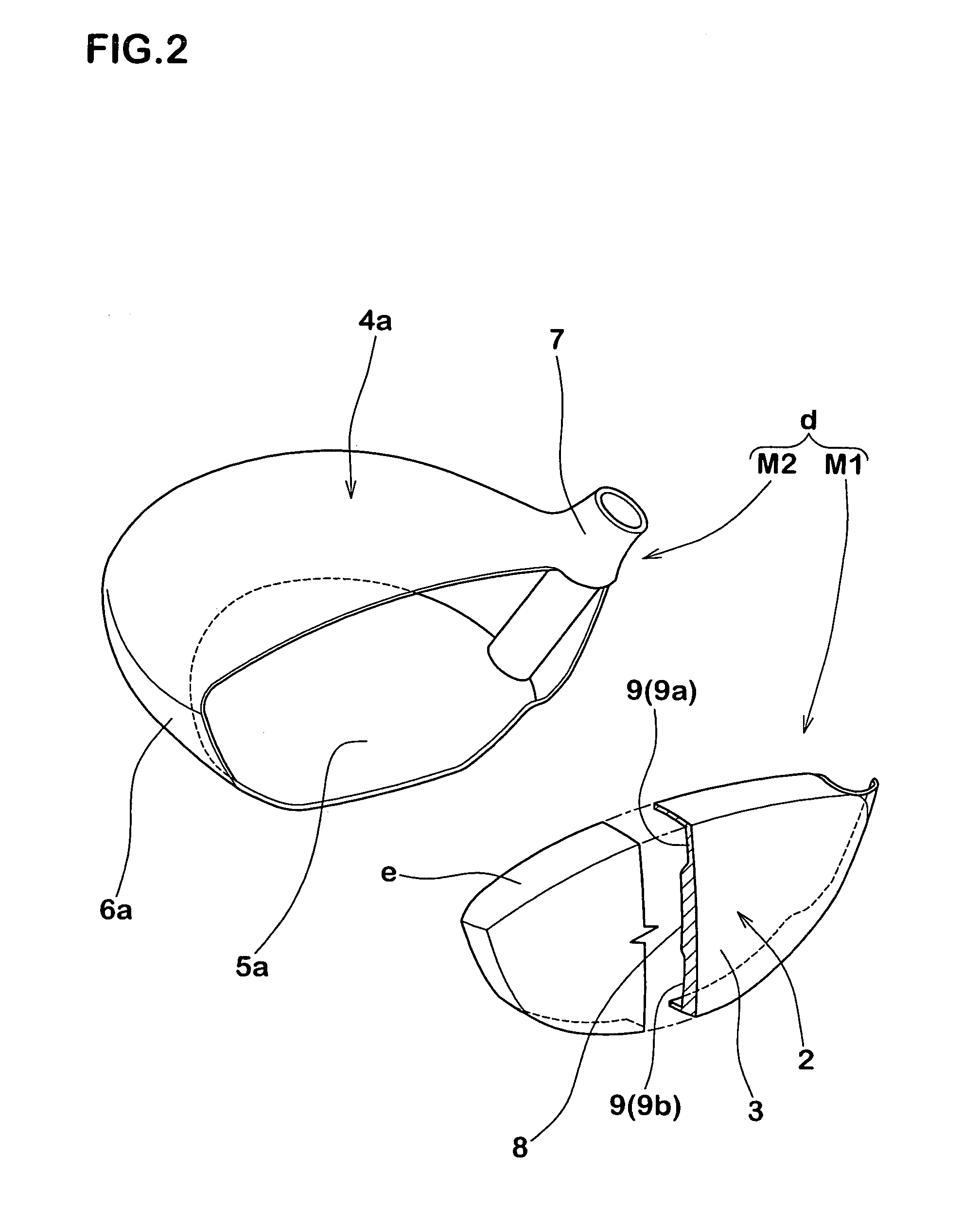
[0046]A driver head with a head volume of 360 cm3, and having a real loft angle of 10 degree and a hook angle of 2 degree is manufactured by way of trial on the basis of the specification in Table 1. Each of the heads is manufactured by welding a face member constituted by a cup-shaped forged product and a head main body constituted by a casted product, as shown in FIG. 2. In this case, Ti-4.5Al-3V-2Mo-2Fe (SP700) is employed as a material of the face member, and Ti-6Al-4V is employed as a material of the head main body, respectively. Further, the wood type golf club having an entire length of 45 inch is manufactured by firmly fixing a shaft to each of the trial heads, and the following tests are executed.

Restitution Coefficient of Head

[0047]The restitution coefficient of the head is measured on the basis of Procedure for Measuring the Velocity Ratio of a Club Head for Conformance to Rule 4-1e, Revision 2 (Feb. 8, 1999) of U.S.G.A. The larger the numeral value is, the better the hea...


PUM


Abstract

This present invention relates to a hollow golf club head comprising a face portion whose front face defines a club face for hitting a ball, wherein said face portion comprises a center portion forming an area having a sweet spot, and a peripheral portion surrounding the center portion and having the thickness smaller than the thickness of said center portion, wherein the thickness of the peripheral portion is reduced from the sole portion side of the head toward the crown portion side.

Description

[0001]This Nonprovisional application claims priority under 35 U.S.C. § 119(a) on Patent Application No(s). 2003-362383 filed in Japan on Oct. 22, 2003, the entire contents of which are hereby incorporated by reference.BACKGROUND OF THE INVENTION[0002]1. Field of the Invention[0003]The present invention relates to a golf club head by which an improvement of carry can be expected.[0004]2. Description of the Related Art[0005]In recent years, there has been proposed a golf club head in which an inner portion is formed hollow. The head mentioned above has a metal face portion for hitting a ball. Further, the face portion includes a center portion having a large thickness and the peripheral portion surrounding the center portion and having a smaller thickness than that of the center portion.[0006]In the head mentioned above, a specific frequency of the head gets close to a specific frequency of the ball. Accordingly, an energy loss generated at a time of collision between the head and th...

Claims


Application Information

Patent Timeline
Patent Type & Authority Patents(United States)
IPC IPC(8): A63B53/04A63B102/32
CPCA63B53/0466A63B2053/0416A63B2053/0462A63B2209/023A63B2053/0408A63B2053/0458A63B53/0408A63B53/0416A63B53/0458A63B53/0462
Inventor OYAMA, HITOSHI
Owner SUMITOMO RUBBER IND LTD
Why Eureka
Try Eureka