Prepless coaxial cable connector

a coaxial cable and connector technology, applied in the direction of coupling devices, two-part coupling devices, electrical apparatus, etc., can solve the problems of unsatisfactory electrical and mechanical connection, a large amount of manual force, and the process of preparing the end of the coaxial cable for installation into the connector requires a modicum of skill and time-consuming

Inactive Publication Date: 2008-03-25
PPC BROADBAND INC
View PDF188 Cites 88 Cited by
  • Summary
  • Abstract
  • Description
  • Claims
  • Application Information

AI Technical Summary

Benefits of technology

[0009]It is a further object of the present invention to provide a coaxial cable connector which eliminates the need to prepare an end of a coaxial cable.
[0011]In a preferred embodiment, the connector further includes an axially movable locking sleeve coupled to the rearward cable receiving end of the connector body for locking the cable in the connector. The connector further preferably includes an annular compression gasket disposed between the locking sleeve and the connector body, which expands in a radially inward direction upon compression between the locking sleeve and the connector body to grip the outer surface of the cable. The locking sleeve preferably includes an outer threaded surface and the connector body further includes an internal threaded sleeve engagement surface cooperating with the sleeve outer threaded surface to facilitate axial movement of the locking sleeve in the connector body.
[0015]As a result of the present invention, the time required to prepare the end of a coaxial cable prior to installation on the connector is drastically minimized if not entirely eliminated.

Problems solved by technology

Needless to say, the process of preparing an end of a coaxial cable for installation into a connector requires a modicum of skill and is somewhat time consuming.
A further problem with current coaxial connectors is that in order to properly attach the connector to the coaxial shielded cable, a good deal of manual force must be applied to push the coaxial shielded cable over the barbs of the post.
During conventional installation, the cable can buckle when the post with the barb is pushed between the foil and the braid and create an unsatisfactory electrical and mechanical connection.
Thus, a mistake made in the preparation process may result in a faulty connector installation.

Method used


Image

  • Prepless coaxial cable connector
  • Prepless coaxial cable connector
  • Prepless coaxial cable connector

Examples


Embodiment Construction

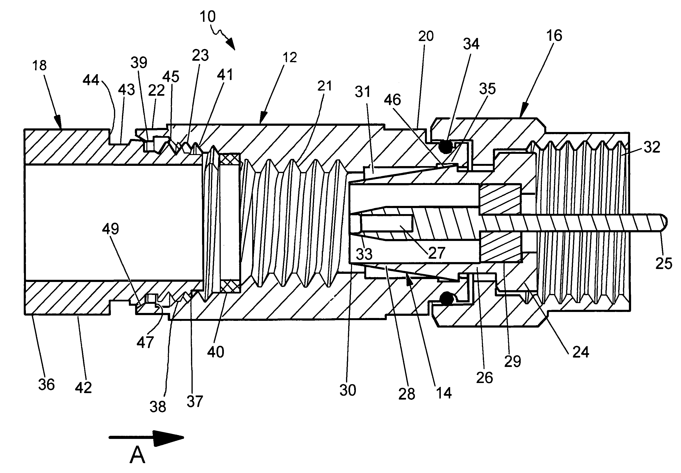
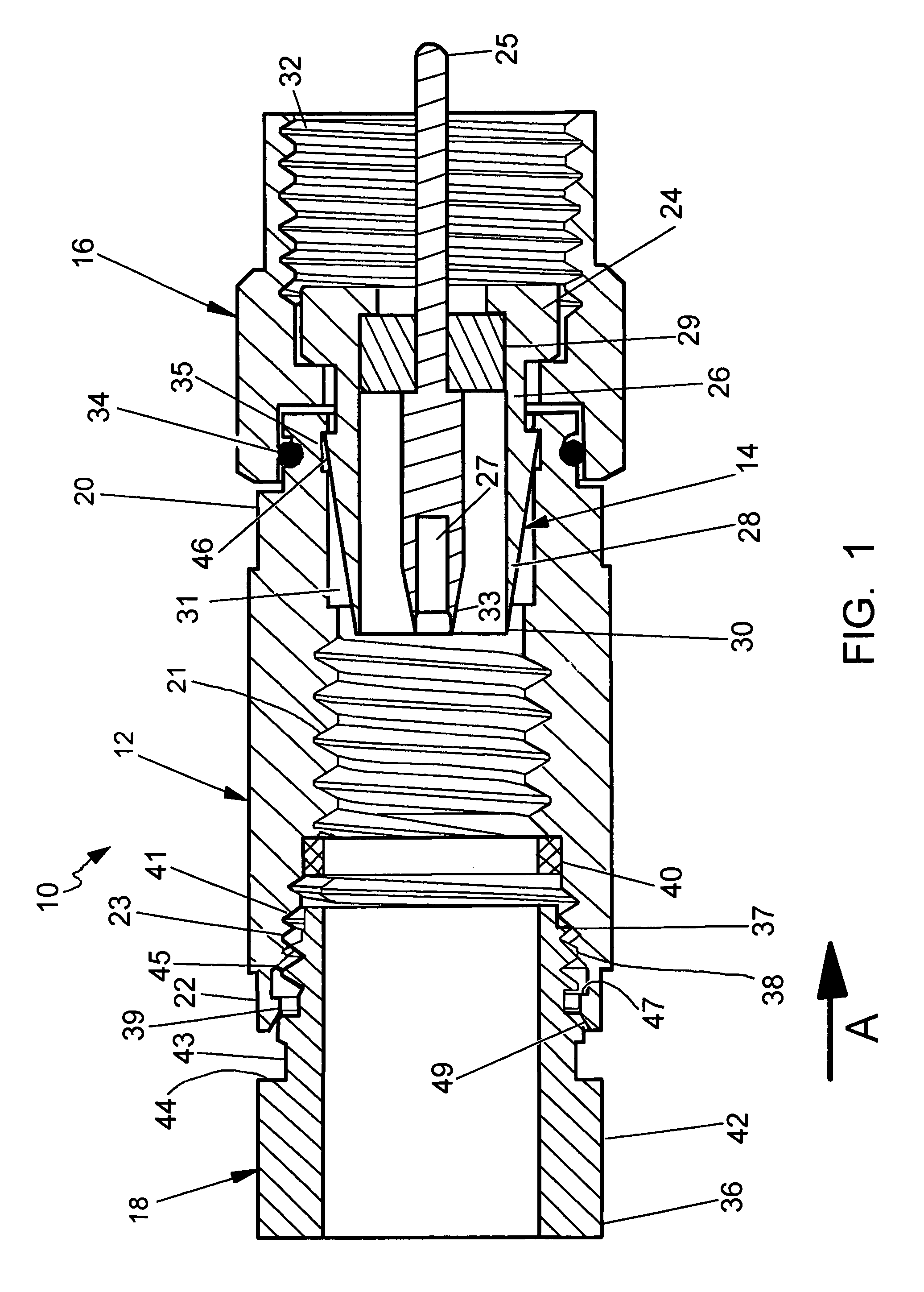
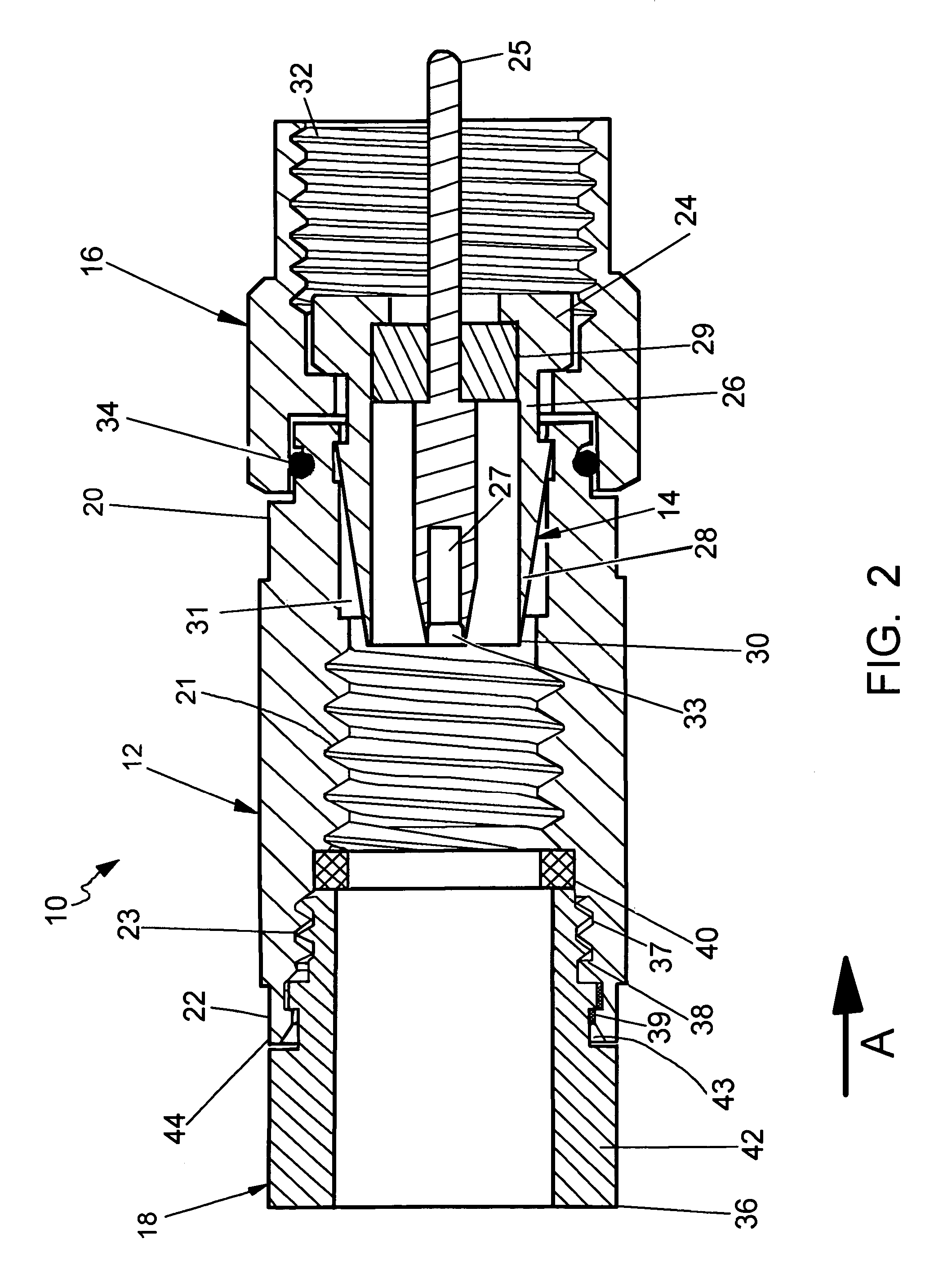
[0021]Referring first to FIGS. 1 and 2, the coaxial cable connector 10 of the present invention is shown. The connector 10 generally includes three components: a connector body 12; an annular post 14; and a rotatable nut 16. The connector 10 further preferably includes an axially movable locking sleeve 18 to help secure the cable to the connector, as will be discussed in further detail below. It is also conceivable that the connector body 12 and the post 14 can be integrated into one component and / or another fastening device other than the rotatable nut 16 can be utilized.

[0022]The connector body 12 is an elongate generally cylindrical member, which is preferably made from plastic to minimize cost. Alternatively, the body 12 may be made from metal or the like. The body 12 has a forward end 20 coupled to the post 14 and the nut 16 and an opposite rearward cable receiving end 22 for insertably receiving the end of a coaxial cable. In this regard, the forward end 20 of the connector bo...


PUM


Abstract

A coaxial cable connector includes a connector body and an annular post coupled to the connector body. The connector body has a rearward cable receiving end and an internal threaded surface defined in the rearward cable receiving end. The internal threaded surface is adapted to threadably engage an outer surface of a coaxial cable. The annular post has a rearward cable insertion end disposed within the connector body, which preferably defines a sharp edge adapted to penetrate an end of the cable as the connector body is threaded on the outer surface of the cable.

Description

CROSS-REFERENCE TO RELATED APPLICATIONS[0001]This application claims the benefit of U.S. Provisional Application No. 60 / 728,494, filed on Oct. 20, 2005.FIELD OF THE INVENTION[0002]The present invention relates generally to connectors for terminating coaxial cable. More particularly, the present invention relates to a coaxial cable connector providing an attachment method which eliminates the need to prepare the end of a coaxial cable.BACKGROUND OF THE INVENTION[0003]It has long been known to use connectors to terminate coaxial cable so as to connect a cable to various electronic devices such as televisions, radios and the like. Prior art coaxial connectors generally include a connector body having an annular collar for accommodating a coaxial cable, an annular nut rotatably coupled to the collar for providing mechanical attachment of the connector to an external device and an annular post interposed between the collar and the nut. A resilient sealing O-ring may also be positioned be...

Claims


Application Information

Patent Timeline
Patent Type & Authority Patents(United States)
IPC IPC(8): H01R9/05H01R24/38H01R24/28
CPCH01R4/5033H01R9/053H01R9/0521H01R9/05
Inventor THOMAS, CHARLES E.THAYER, BRIAN T.
Owner PPC BROADBAND INC
Why Eureka
Try Eureka