Rail-car unloading apparatus and method

a technology for unloading apparatus and rail cars, which is applied in the directions of transportation and packaging, railway components, and reprocessing, etc. it can solve the problems of high cost of transporting bulk materials, difficult to justify expanding into new geographical areas to build new fixed unloading stations, and difficult to maintain

Inactive Publication Date: 2008-04-01
ASHROSS
View PDF12 Cites 16 Cited by
  • Summary
  • Abstract
  • Description
  • Claims
  • Application Information

AI Technical Summary

Problems solved by technology

These unloading stations are very costly to build and maintain and, as a result, it is often difficult to justify expanding into new geographical areas to build new fixed unloading stations.
Furthermore, due to the limited proximity locations of the unloading stations, their can also be high cost in transporting the bulk material in dump trucks from the unloading stations to a final destination.
However, such attempts have not matched the efficiency of unloading rail cars at the fixed unloading stations.
This conveyer system may be efficient for moving bulk material from a single rail car; however, time is wasted for re-set up between each rail car since the conveyer system requires retracting and re-set up to begin conveying the material from a subsequent rail car.
Further, since the conveyer system is linear, time is wasted in positioning and aligning the conveyer bottom end to the appropriate location where the bulk material is dumped from the rail car.
In addition, the linear type of conveyer system is limited to bottom dumping from a single shoot in the rail car and, further, the flow of materials from the shoot may have to be restricted in order to avoid over-flow of the material onto the linear type of conveyer system.
Although this system facilitates removing the bulk material at locations other than a fixed unloading station, this system is limited in the speed by which the trackhoe can remove the bulk material from the rail car.
Further, this system is inefficient in initial set-up time and the set-up time required for unloading subsequent rail cars.
Additionally, trackhoes cannot remove all the material from the rail cars and, therefore, additional steps often must be taken to completely clean the material from the rail car, causing additional man-power and wasted time.

Method used


Image

  • Rail-car unloading apparatus and method
  • Rail-car unloading apparatus and method
  • Rail-car unloading apparatus and method

Examples


Embodiment Construction

[0031]Reference will now be made to the exemplary embodiments illustrated in the drawings, and specific language will be used herein to describe the same. It will nevertheless be understood that no limitation of the scope of the invention is thereby intended. Alterations and further modifications of the inventive features illustrated herein, and additional applications of the principles of the inventions as illustrated herein, which would occur to one skilled in the relevant art and having possession of this disclosure, are to be considered within the scope of the invention.

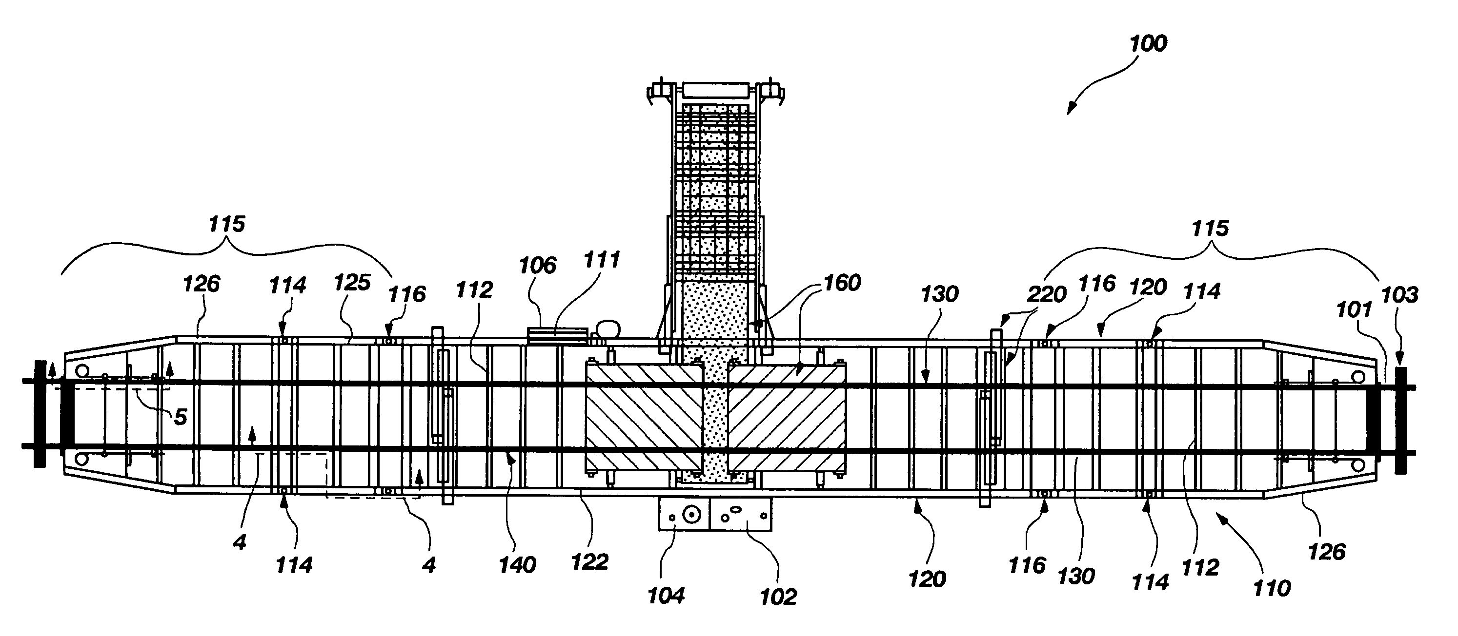
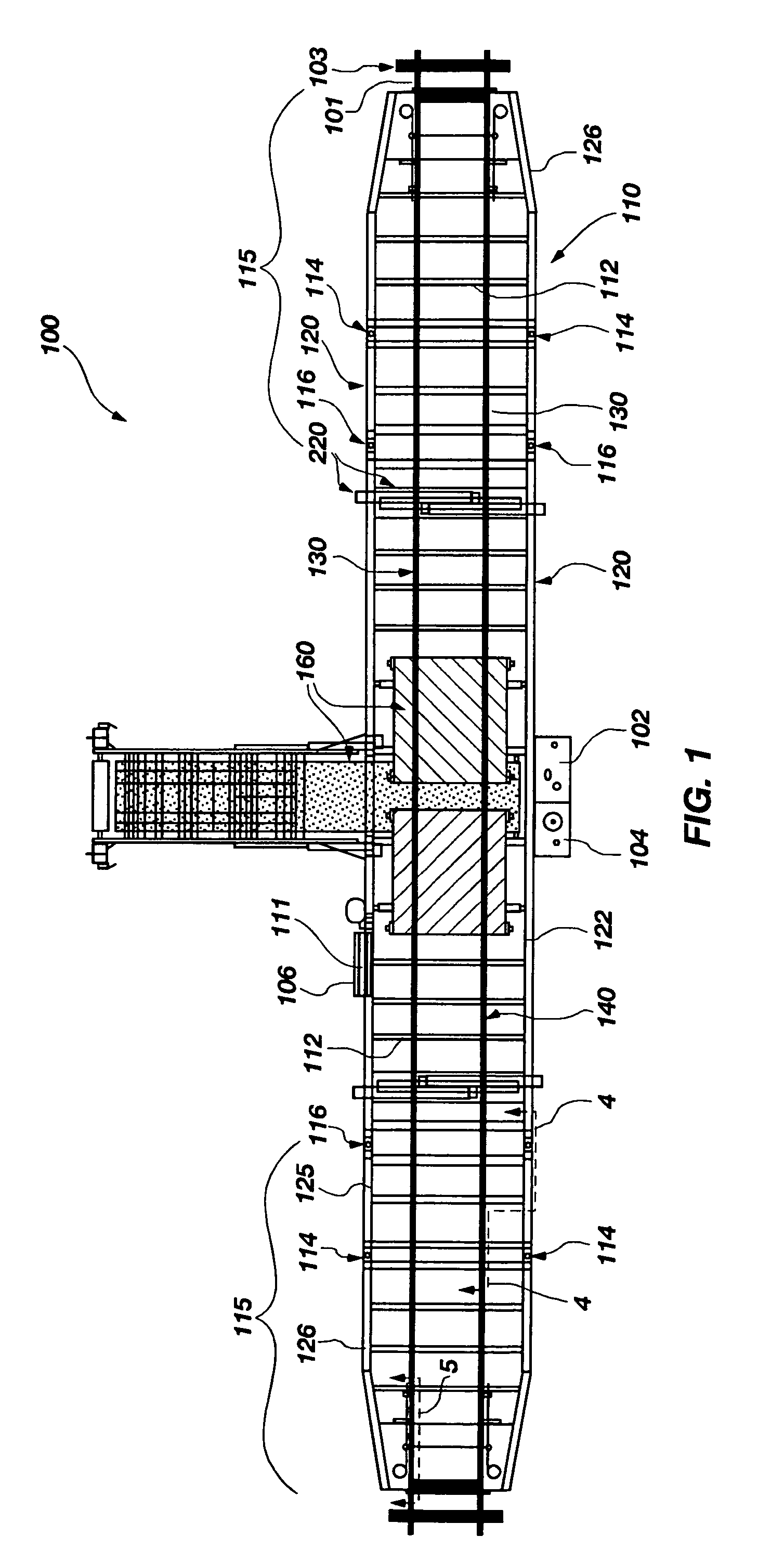
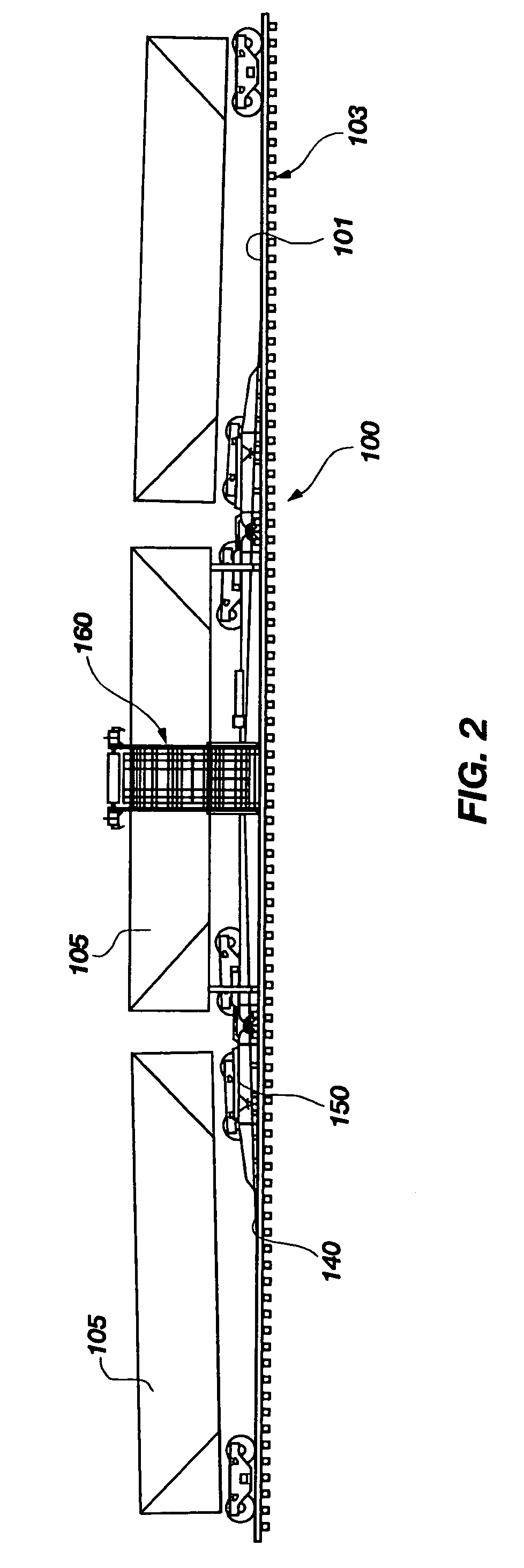
[0032]FIGS. 1 and 2 illustrate simplified top and side views, respectively, of a rail-car unloading machine 100 according to an embodiment of the present invention. Such a rail-car unloading machine 100 includes a frame structure 110 with parallel rails 140 coupled thereto. The rail-car unloading machine 100 also can include an engine 102, a hydraulic pump 104, a controller 106, a hydraulic retraction system 150,...


PUM


Abstract

A rail-car unloading apparatus and method for the same configured to be positioned over fixed rails of a railroad track. The rail-car unloading apparatus includes a frame structure and two parallel rails. The frame structure includes two outer main beams extending substantially parallel with two inner main beams. The two outer main beams are coupled to the two inner main beams with lateral supports. The two inner main beams include tapered end portions at opposite ends thereof and the two inner main beams are configured to extend over and to be positioned against the fixed rails along substantially an entire length of the two inner main beams. The two parallel rails each include a rail length respectively coupled to the two inner main beams of the frame structure. The rail length of each of the two parallel rails is configured to be positioned over the fixed rails with substantially an entire portion of the rail length configured to be positioned over and against the two inner main beams.

Description

[0001]This application claims priority to Provisional Patent Application No. 60 / 534,945 filed on Jan. 8, 2004, in the United States Patent and Trademark Office.FIELD OF THE INVENTION[0002]The present invention relates generally to unloading rail cars and, more particularly, the present invention relates to an unloading system for unloading bulk material dropped from an under-carriage of a rail car.BACKGROUND OF THE INVENTION[0003]Typically, unloading stations for unloading rail cars are made to be in fixed locations. Such fixed unloading stations are often deep pits with concrete side walls with conveyers made to catch material dropped from the rail cars, conveying the material upward out of the pits to, for example, load into dump trucks for transporting elsewhere, to stock pile the material or to feed other conveyer systems. These unloading stations are very costly to build and maintain and, as a result, it is often difficult to justify expanding into new geographical areas to bui...

Claims


Application Information

Patent Timeline
Patent Type & Authority Patents(United States)
IPC IPC(8): B65G67/00B61D47/00B65G15/26B65G47/18B65G67/24
CPCB61D47/00B65G47/18B65G67/24
Inventor ASH, LLOYD
Owner ASHROSS
Why Eureka
Try Eureka