Housingless washer

a washer and housing technology, applied in the field of washers, can solve the problems of large enclosure, difficult maintenance and retooling of the machine, unwieldy and relatively expensive, etc., and achieve the effect of large enclosur

Inactive Publication Date: 2008-04-08
CINETIC AUTOMATION
View PDF121 Cites 4 Cited by
  • Summary
  • Abstract
  • Description
  • Claims
  • Application Information

AI Technical Summary

Problems solved by technology

Although such enclosures have proven to be quite durable and relatively easy to fabricate, they are large, unwieldy and relatively costly.
Access to the machines within the enclosure is oftentimes limited thereby making maintenance and retooling of the machines difficult.
Furthermore, because the majority of the machines used to wash, rinse and dry the part are located within the enclosure, the machines are detrimentally exposed to the harsh solvent spray throughout their life.
However, the restricted openings hinder access to the interior volume of the enclosure.
However, due to the size and weight of the requisite enclosure, mechanical lifts or cranes are usually needed to raise the enclosure.

Method used


Image

  • Housingless washer
  • Housingless washer
  • Housingless washer

Examples


Embodiment Construction

[0017]The following description of the preferred embodiment(s) is merely exemplary in nature and is in no way intended to limit the invention, its application, or uses.

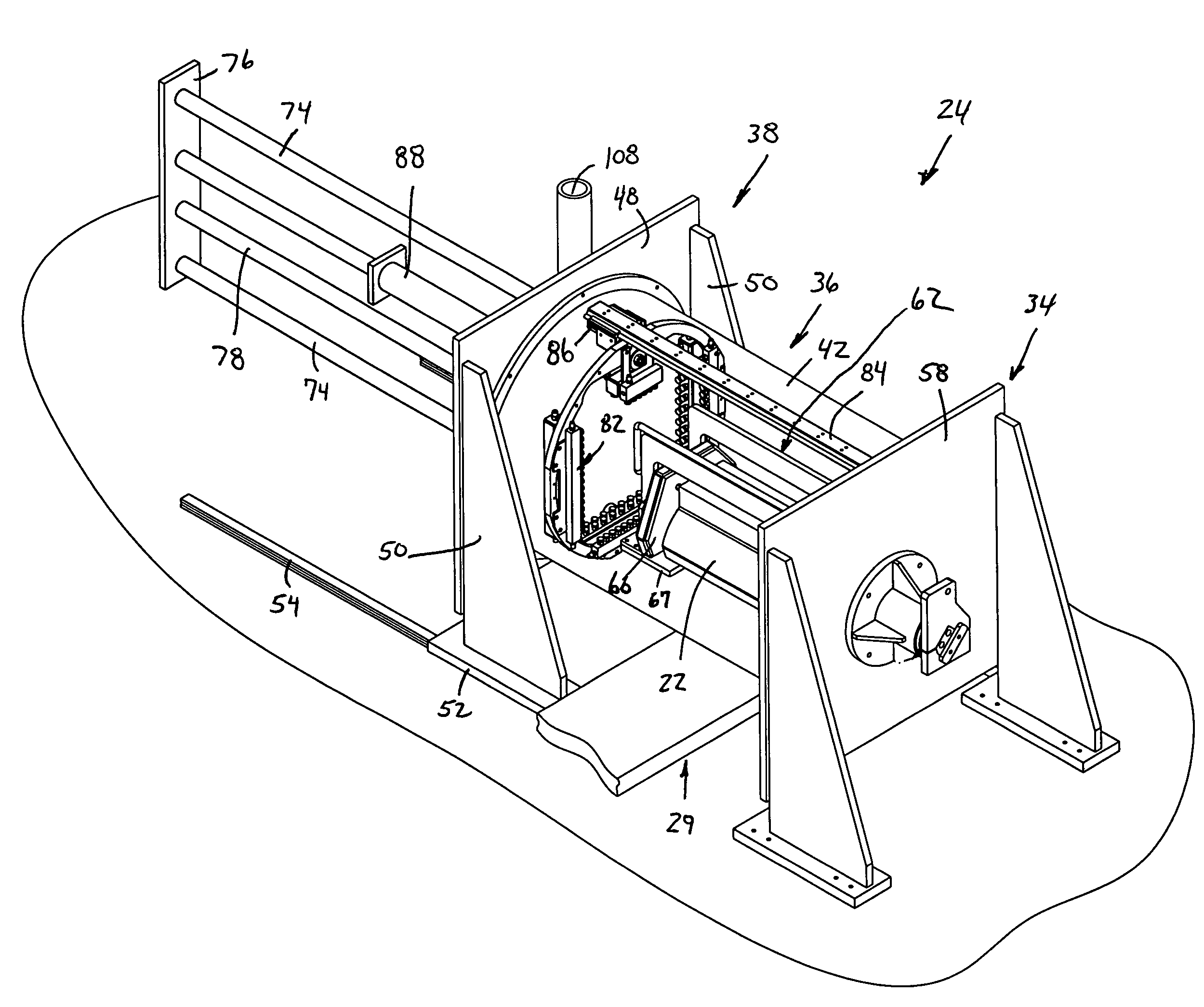
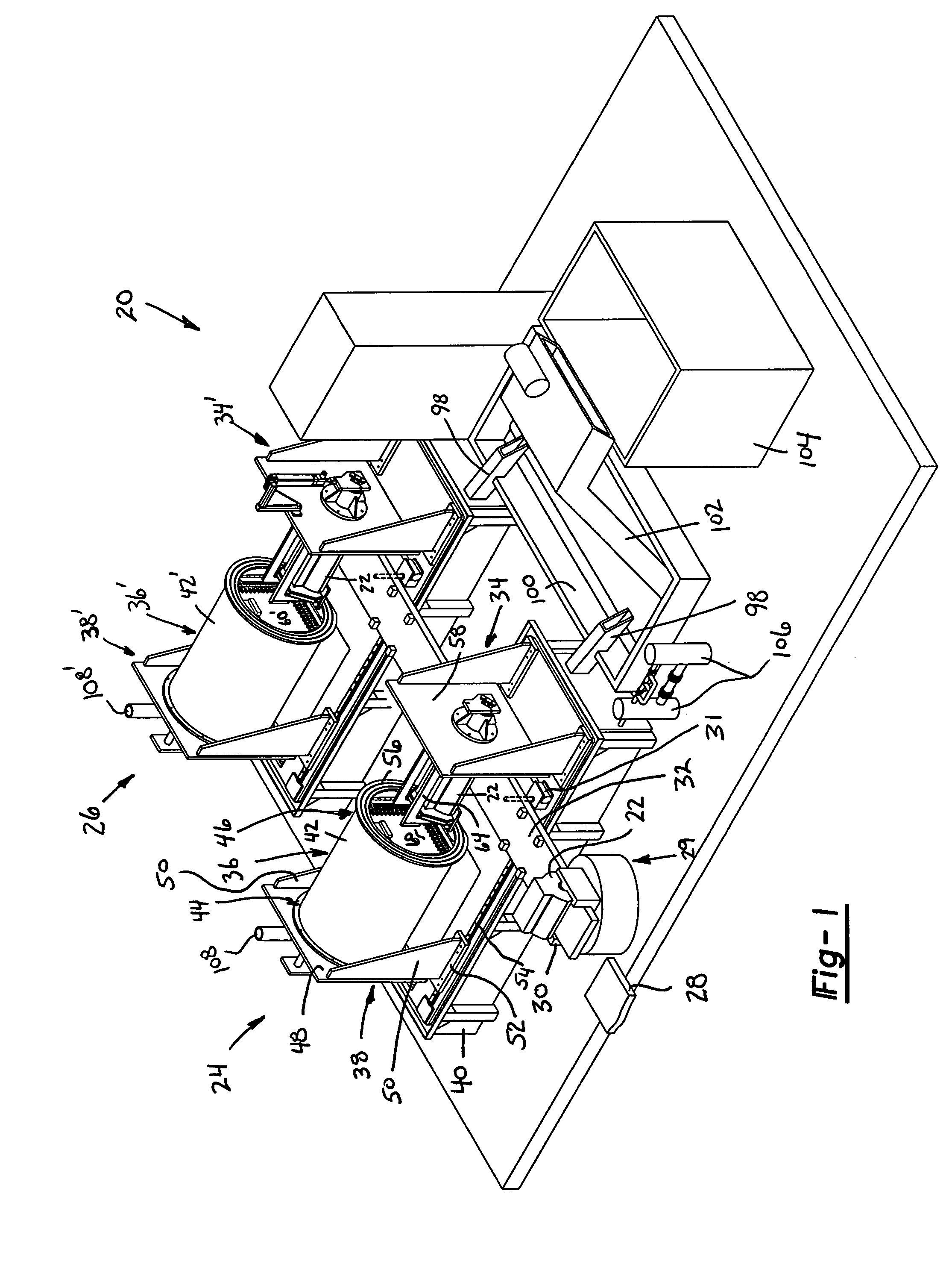
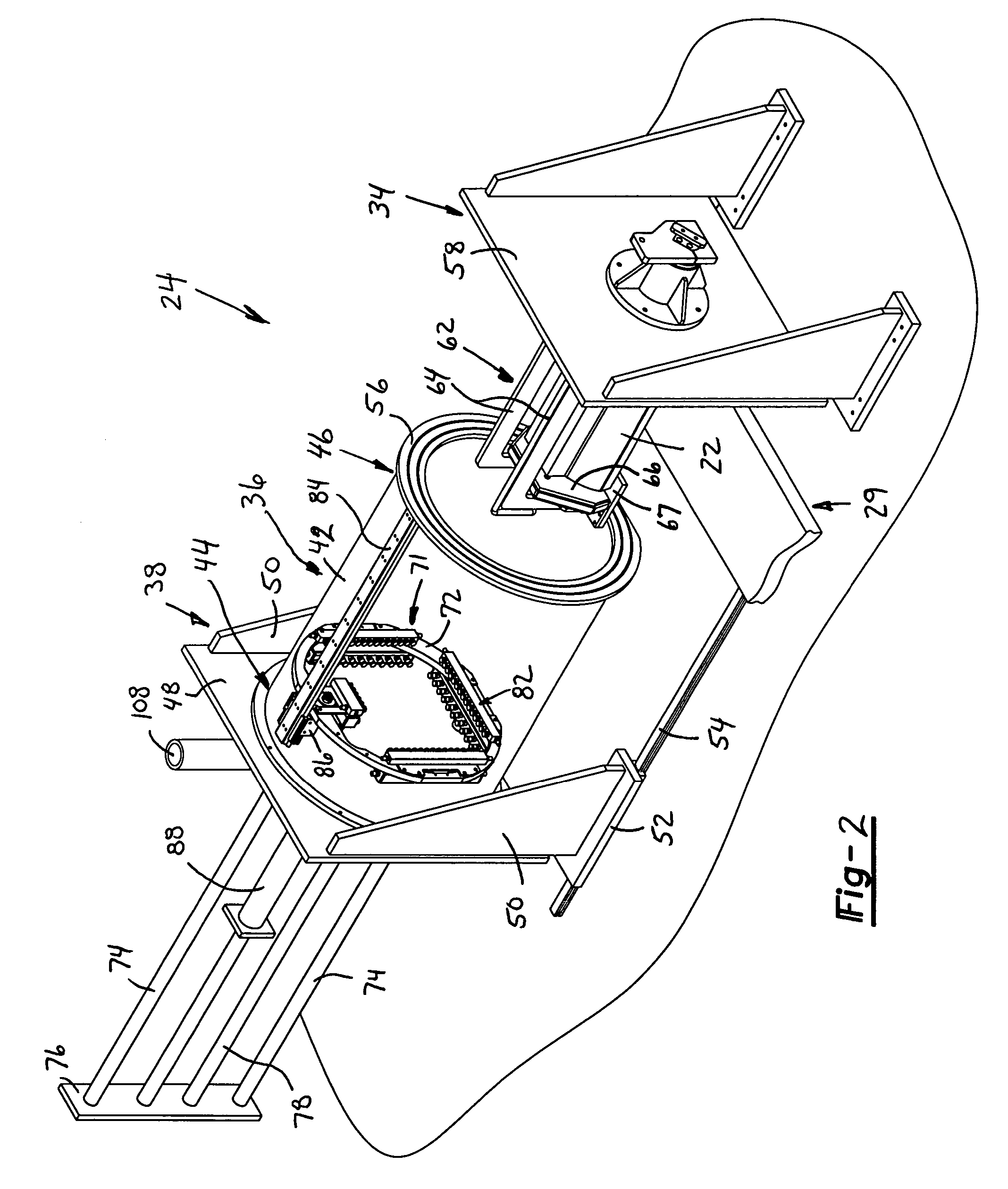
[0018]Referring to FIG. 1, a preferred embodiment of a parts washer 20 for use in an industrial manufacturing plant to clean industrial parts or workpieces such as automotive vehicle powertrain components, including a part 22 or the like is shown. Parts washer 20 operates as a cleaning station typically positioned after a machining station (not shown) where the part has been machined by a mill, a lathe, a grinding machine or a similar industrial tool. During the machining process, lubrication, grease, dirt and burrs often adhere to the walls of internal passageways and the external surface of the machined part.

[0019]Parts washer 20 includes a washing station 24 and a drying station 26 positioned adjacent to one another. A conveyor 28 transports part 22 from a machining center (not shown) to a transfer system 29. Trans...


PUM


Abstract

An industrial parts washer includes a stand adapted to support a part, a chamber selectively movable from a first position clear of the part to a second position engaging the stand where the chamber forms a closed volume encapsulating the part. A nozzle is positioned within the chamber to supply pressurized fluid for cleaning the part. The industrial parts washer may include a washing station positioned adjacent a drying station where each of the washing and drying stations include chambers selectively movable to enclose the part.

Description

BACKGROUND AND SUMMARY OF THE INVENTION[0001]The present invention generally relates to a washer for industrial parts and, more particularly, to a washer which eliminates the need for a large enclosure.[0002]Manufactured industrial parts, such as machined metallic components, become coated with cutting fluids, lubricating oils, machine coolants, metal fragments and other contaminants during the manufacturing process. For example, metal cutting operations often include the steps of applying a lubricant to the cutting tool and part being machined. Lubricant residue and metal chips often adhere to the surface of the part. Industrial parts washers are used to remove undesired contaminants and clean the part prior to use.[0003]Industrial parts washers typically include one or more processing zones for washing, rinsing, drying and other steps for cleaning the parts. A conveyor typically transports the parts through the processing zones from one end of the washer to the other. Because indu...

Claims


Application Information

Patent Timeline
Patent Type & Authority Patents(United States)
IPC IPC(8): B08B3/02
CPCB08B3/02
Inventor STOCKERT, DAVID L.EVANS, TIMOTHY B.SOBECK, ROBERT J.
Owner CINETIC AUTOMATION
Why Eureka
Try Eureka