Organic electroluminescence display panel including a gas barrier laminate between a substrate and an organic electroluminescence element

a technology of organic electroluminescence and substrate, applied in the field of organic electroluminescence display panels, can solve the problems of difficult to completely prevent the deterioration of organic el elements, difficult to completely rid the inorganic barrier film of such pinholes, and prominent character deterioration of organic el display panels, etc., to achieve a high-reliable gas barrier, impart gas barrier properties to the laminate body, and favorable gas barrier properties

Inactive Publication Date: 2008-04-08
PIONEER CORP
View PDF20 Cites 10 Cited by
  • Summary
  • Abstract
  • Description
  • Claims
  • Application Information

AI Technical Summary

Benefits of technology

[0009]The invasion of vapor (moisture, oxygen, etc.) via the exposed parts of the polymer compound layers can be prevented as a result of plasma-processing the exposed parts. Thus, the gas barrier properties of the organic EL display panel can be improved.
[0011]The plasma-processing is applied to the polymer compound layers so that gas barrier properties are imparted to the polymer compound layers. Accordingly, a highly reliable gas barrier laminate can be formed easily, and, therefore, an organic EL display panel with favorable gas barrier properties can be obtained.
[0013]The polymer compound layers are subjected to plasma processing at the same time as the plasma processing in the first display electrode formation step, and therefore the number of steps to fabricate the organic EL display panel can be reduced.

Problems solved by technology

In particular, characteristic deterioration is prominent in organic EL display panels that use a plastic film substrate, i.e., light emission characteristics such as the brightness and hue deteriorate.
However, pinholes occur in this inorganic barrier film.
Thus, it is difficult to rid the inorganic barrier film of such pinholes completely.
Consequently, even when an inorganic barrier film is provided on the resin substrate, it is impossible to completely prevent deterioration of the organic EL element.

Method used


Image

  • Organic electroluminescence display panel including a gas barrier laminate between a substrate and an organic electroluminescence element
  • Organic electroluminescence display panel including a gas barrier laminate between a substrate and an organic electroluminescence element
  • Organic electroluminescence display panel including a gas barrier laminate between a substrate and an organic electroluminescence element

Examples


Embodiment Construction

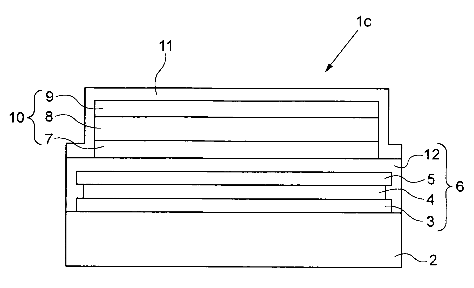
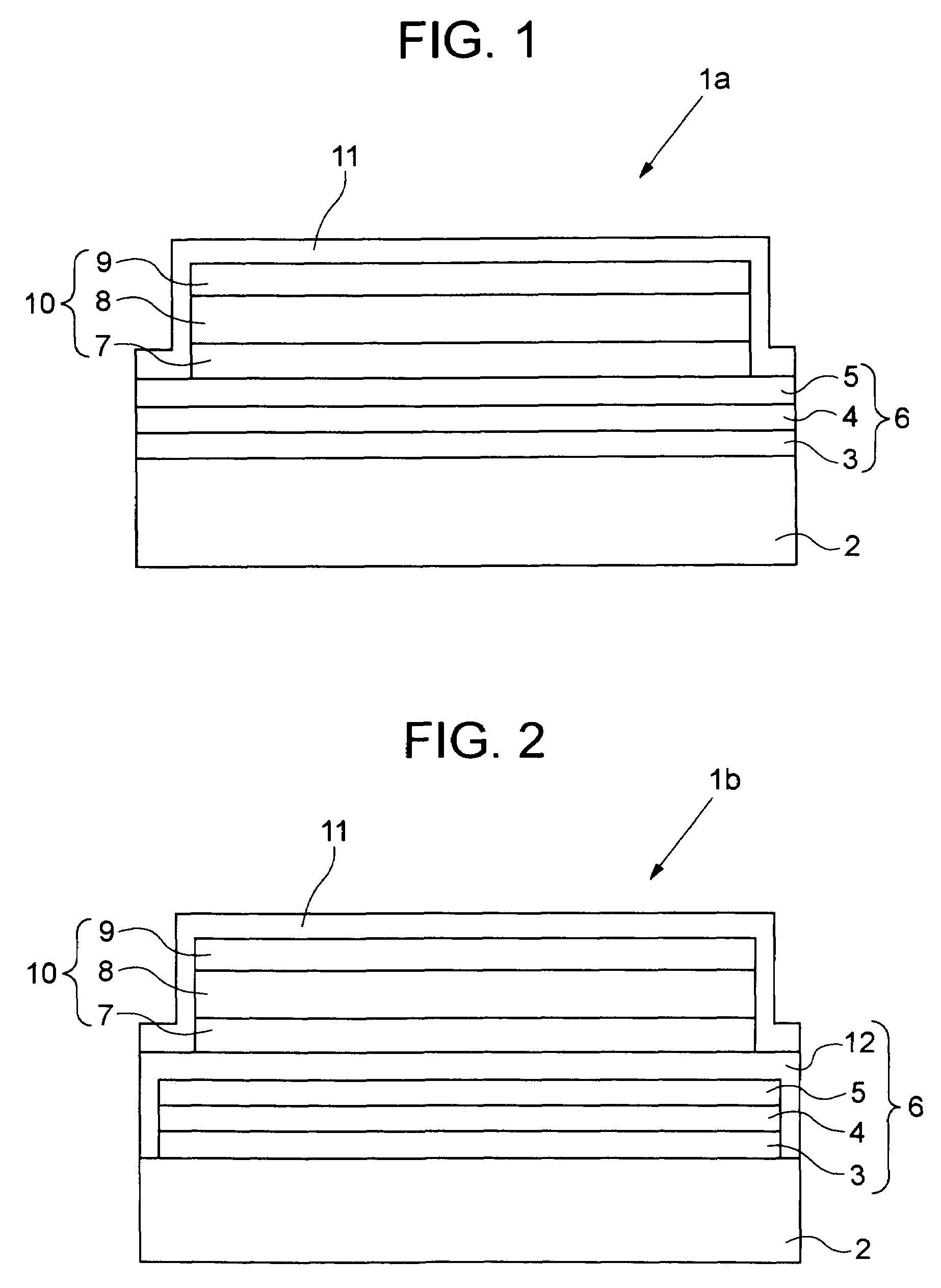
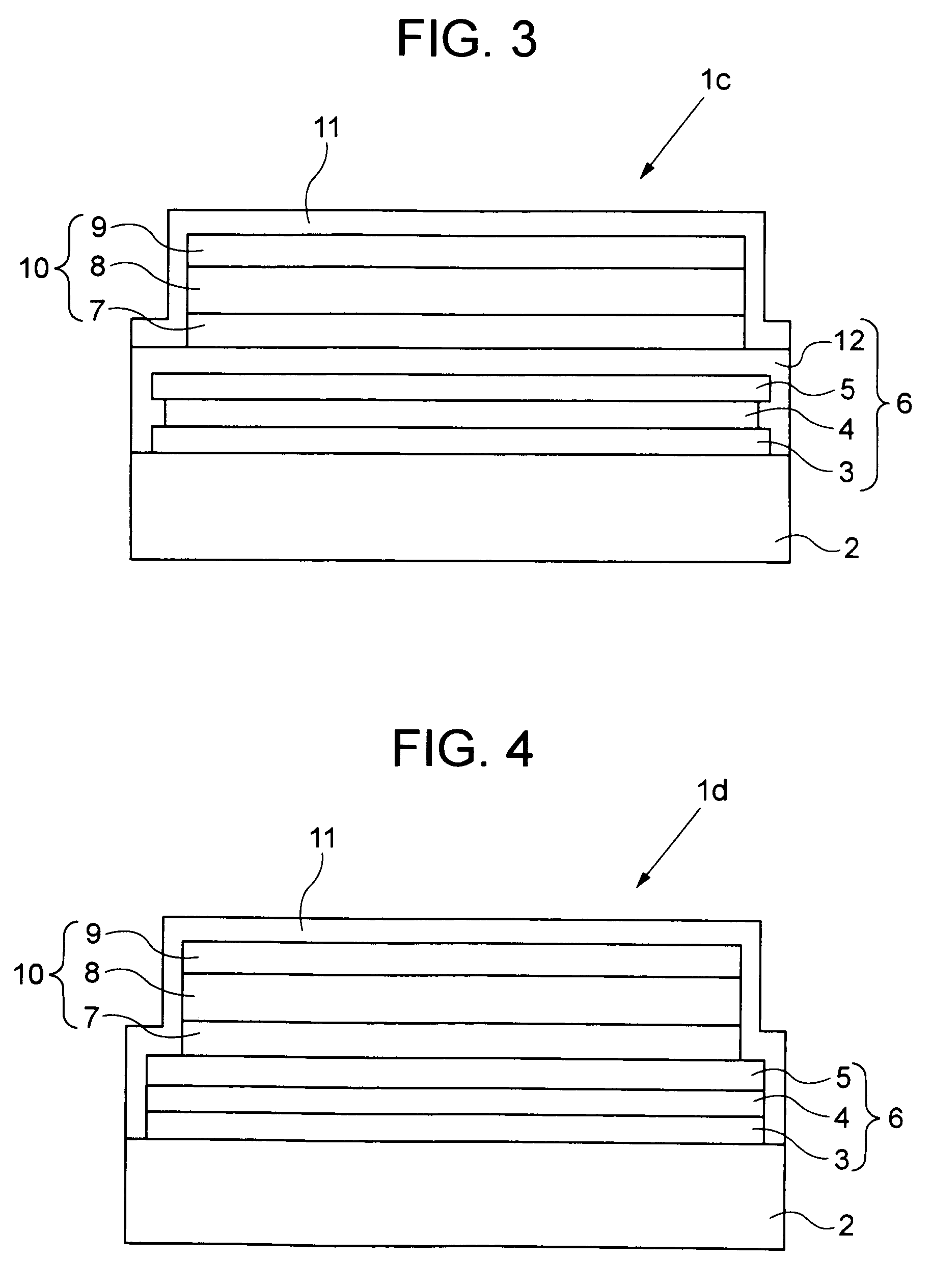
[0022]An embodiment of the organic EL display panel of the present invention will now be described in detail with reference to the attached drawings. The same or similar reference numbers are assigned to the same or similar parts in different drawings. It should be noted that although drive components, wiring and so forth required for the operation of the display panel are included in the organic EL display panel, these parts are omitted from the following description.

[0023]As shown in FIG. 1, an organic EL display panel 1a includes a resin substrate 2. The resin substrate 2 is, for example, made from polyethylene terephthalate, polyethylene-2,6-naphthalate, polycarbonate, polysulphone, polyethersulphone, polyetheretherketone, polyphenoxyether, polyarylate, fluorine resin, polypropylene, polyethylene naphthalate, or polyolefin. The resin substrate 2 may be a flexible film.

[0024]A gas barrier layer 6 is formed on the resin substrate 2. The bas barrier layer 6 includes two inorganic b...


PUM

PropertyMeasurementUnit
organicaaaaaaaaaa
electroluminescenceaaaaaaaaaa
lengthaaaaaaaaaa

Abstract

An organic electroluminescence display panel includes an organic electroluminescence element and a resin substrate that supports the organic electroluminescence element. A gas barrier laminate is formed between the resin substrate and the organic electroluminescence element. The gas barrier laminate includes two or more inorganic barrier layers and one or more polymer compound layers each provided between the inorganic barrier layers. The exposed parts of the polymer compound layer that are not covered by the inorganic barrier layers are subjected to plasma processing. The exposed parts may be covered by a cover layer or a sealing layer that affords gas barrier properties.

Description

BACKGROUND OF THE INVENTION[0001]1. Field of the Invention[0002]The present invention relates to an organic electroluminescence display panel and to a fabrication method thereof.[0003]2. Description of the Related Art[0004]An organic electroluminescence display panel (hereinafter called an ‘organic EL display panel’) includes an organic electroluminescence element (hereinafter called an ‘organic EL element’). In the organic EL element, an organic functional layer made from an organic compound material that affords electroluminescence is interposed between an anode and a cathode. The organic functional layer is a laminate body which can have a variety of configuration. For example, a certain organic functional layer has a three-layer structure, which includes a light emission layer made from an organic compound material affording electroluminescence, a light emission layer and an organic electron transport layer. Another organic functional layer has another three-layer structure whic...

Claims


Application Information

Patent Timeline
Patent Type & Authority Patents(United States)
IPC IPC(8): H01J1/62H01J63/04H05B33/04C23C14/06C23C16/30H01L51/00H01L51/50H01L51/52H05B33/00H05B33/02H05B33/10H05B33/14
CPCH01L51/0097H01L51/5237H01L2251/5338Y02E10/549Y02P70/50H10K77/111H10K50/8445H10K50/844H10K2102/311H05B33/04H05B33/10
Inventor YOSHIZAWA, TATSUYA
Owner PIONEER CORP
Why Eureka
Try Eureka