Unitary hydroformed roof support pillar

a hydroformed, roof support technology, applied in roofs, transportation and packaging, vehicle arrangements, etc., can solve the problems of increasing the weight of a vehicle, increasing the cost of manufacturing b-pillars, and the inability of b-pillars of conventional design to meet stringent test requirements for roof strength and side impact performance, etc., to achieve the effect of facilitating spot welding

Active Publication Date: 2008-04-15
FORD GLOBAL TECH LLC +1
View PDF38 Cites 40 Cited by
  • Summary
  • Abstract
  • Description
  • Claims
  • Application Information

AI Technical Summary

Problems solved by technology

However, the use of high strength alloys and thicker sheet metal may increase the weight of a vehicle and also increases the cost to manufacture the B-pillar.
Even with the use of thicker alloy components, B-pillars of conventional design may not always meet stringent test requirements for roof strength and side impact performance.
This proposed design presents a manufacturing problem in that the closed box section of the parts precludes spot welding assembly techniques.
Also, the longitudinal thickness of the hydroformed tube portion between vehicle doors is objectionable from a styling standpoint.
However, these proposed designs require reinforcing brackets to connect the B-pillar to a roof rail.
In addition, the B-pillar is not reinforced by the roof rail and rocker panel members.
In addition, the width of the B-pillar in the longitudinal vehicle direction limits styling and adversely impacts vehicle appearance.
Prior art methods of hydroforming roof support pillars face technical barriers relating to the hydroforming procedure, methods of joining hydroformed components and packaging constraints.
In particular, it is difficult for a hydroformed tube that has a uniform perimeter to accommodate desired section variations for vehicle styling.
Packaging constraints for B-pillars include providing clearance for seatbelt retractors and adequate mounting surfaces for door latch and hinge reinforcements.

Method used


Image

  • Unitary hydroformed roof support pillar
  • Unitary hydroformed roof support pillar
  • Unitary hydroformed roof support pillar

Examples


Embodiment Construction

)

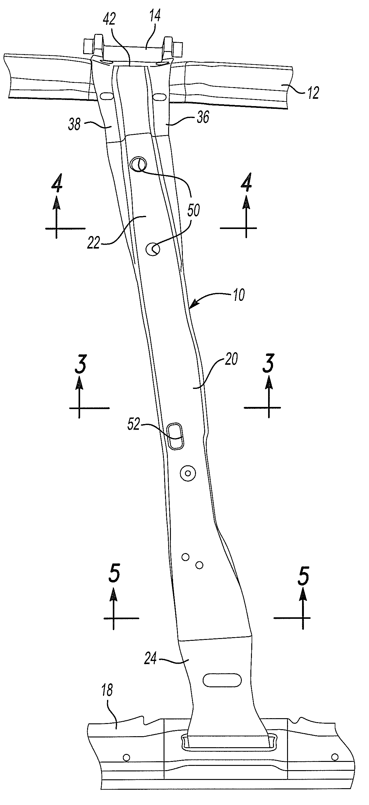
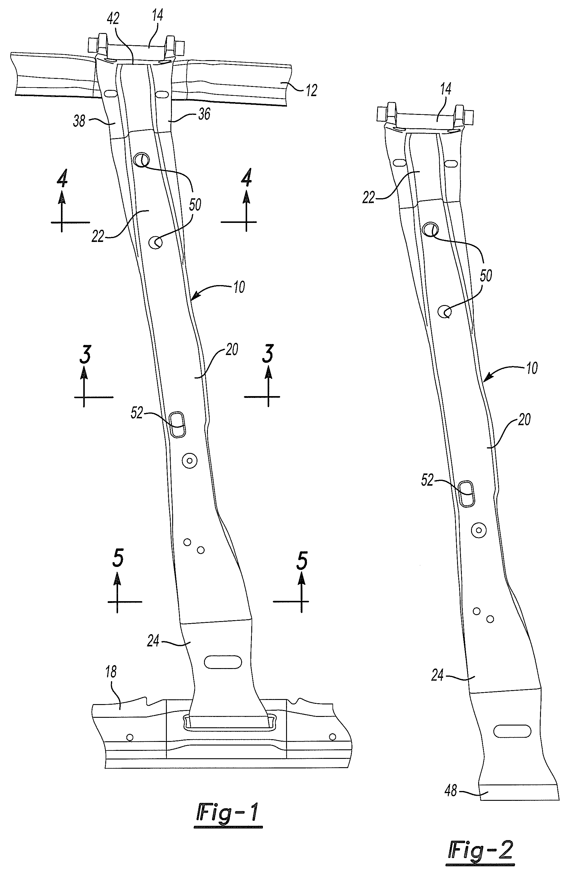
[0027]Referring to FIG. 1, a one-piece B-pillar 10 is shown attached to a roof rail 12 and roof bow 14. The B-pillar 10 is also attached to a rocker 18.

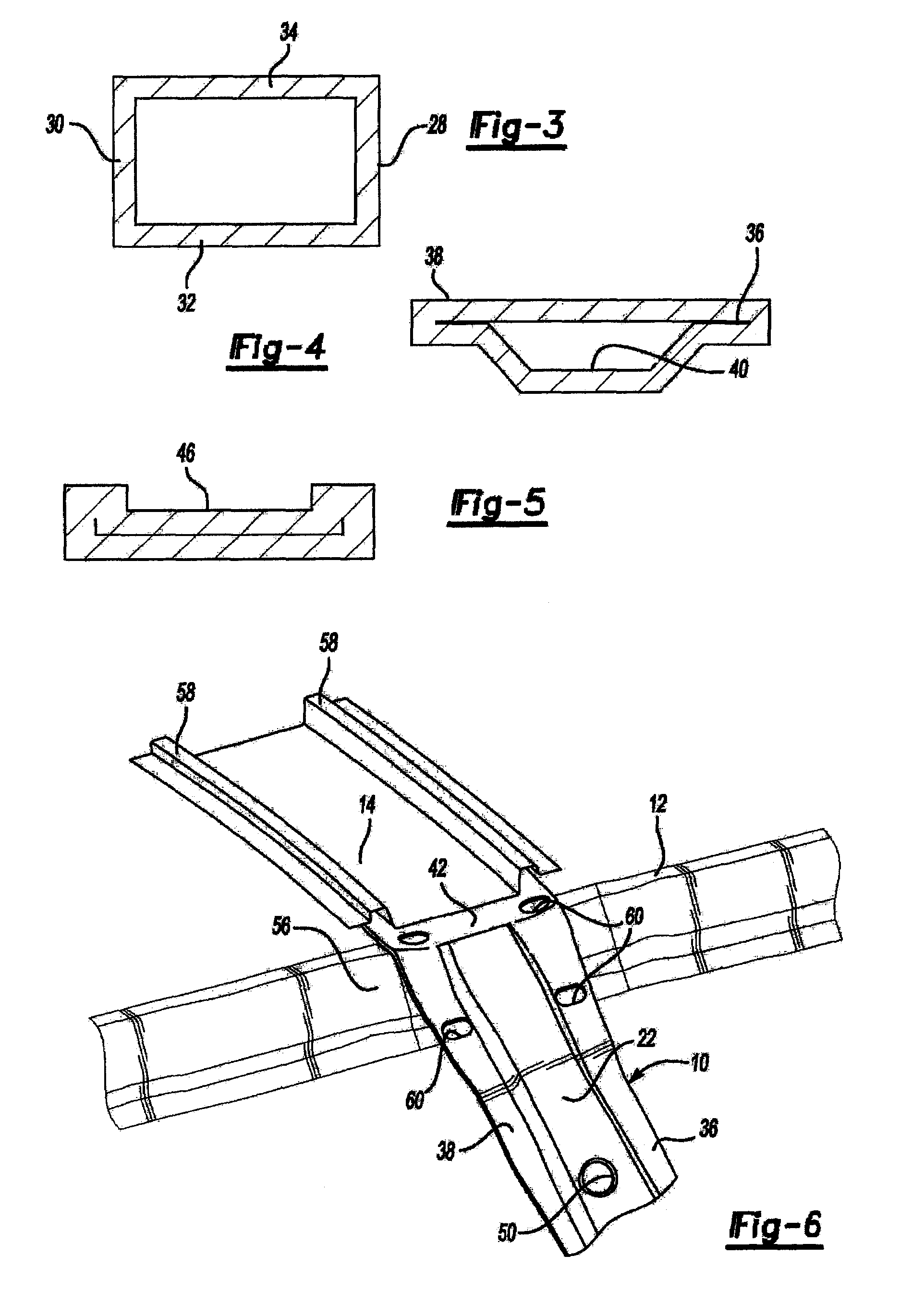
[0028]The B-pillar 10 has a middle portion 20 and an upper portion 22 extending upwardly from the middle portion 20. A lower portion 24 extends downwardly from the middle portion 20. Referring to FIG. 3, which is a cross section taken through the middle portion 20, the cross section of the B-pillar 10 in that area includes a front wall 28, a rear wall 30, and outer wall 32 and an inner wall 34. The four walls 28-34 form a substantially rectangular box shaped beam.

[0029]Referring to FIG. 4, a cross section taken through the upper portion 22 of the B-pillar 10 is illustrated. A front flange 36 and a rear flange 38 extend forwardly and rearwardly, respectively, from a trapezoidal section 40. The trapezoidal section 40 extends upwardly as a continuation of the walls 28-34 with the front wall 28 and rear wall 30 converging toward the out...


PUM


Abstract

A one-piece B-pillar having a front flange and a rear flange formed on an upper portion of the B-pillar. The front and rear flanges extend forwardly and rearwardly from a trapezoidal section of the B-pillar. An inner concave portion is provided in a lower portion of the B-pillar. The one-piece B-pillar is secured to the outer and upper surfaces of a roof rail and to the outer surface of a rocker to provide side impact strength. The B-pillar is hydroformed in one-piece to provide superior strength for roof crush performance. The tubular portion of the B-pillar is partially collapsed to form a trapezoidal section in the upper portion of the B-pillar.

Description

CROSS-REFERENCE TO RELATED APPLICATIONS[0001]This application claims the benefit of U.S. provisional application Ser. No. 60 / 687,666 filed Jun. 6, 2005.BACKGROUND OF THE INVENTION[0002]1. Field of the Invention[0003]The present invention relates to a unitary hydroformed roof support pillar for a vehicle.[0004]2. Background Art[0005]Roof support pillars support the roof of a vehicle and are located between the windows and doors of a vehicle. Roof support pillars are frequently identified as A, B, C and in some instances D-pillars depending on the vehicle style. A B-pillar is generally located immediately behind the front door of a vehicle. The B-pillar is an important element in determining roof strength and the degree of side impact intrusion.[0006]Passenger vehicle designs are tested for roof strength and side impact strength. Conventional B-pillars are fabricated as multiple stamped sheet metal parts that are generally spot welded together. It is possible to improve the strength o...

Claims


Application Information

Patent Timeline
Patent Type & Authority Patents(United States)
IPC IPC(8): B62D25/04
CPCB62D25/04B62D25/06B62D27/02
Inventor CHEN, XIAOMINGFARUQUE, OMARGUIMBERTEAU, THIERRYKUO, EVERETTMEHTA, RAJWAGNER, DAVIDGERICKE, DEANSZALAY, DANIEL
Owner FORD GLOBAL TECH LLC
Why Eureka
Try Eureka