Plasma display panel

a technology of display panel and plasma, which is applied in the field of plasma display panel, can solve the problems that the discharge voltage may adversely affect the overall performance, and achieve the effect of reducing the differences in the firing voltage and increasing the overall range of the voltag

Inactive Publication Date: 2008-04-29
SAMSUNG SDI CO LTD
View PDF2 Cites 12 Cited by
  • Summary
  • Abstract
  • Description
  • Claims
  • Application Information

AI Technical Summary

Benefits of technology

[0011]The present invention provides a PDP that may reduce differences in firing voltages for different colored discharge cells, thereby increasing the overall range of a voltage that may used for the firing voltage.

Problems solved by technology

Further, since the phosphor layers may exhibit dissimilar illumination efficiencies according to the type of discharge gas used and discharge voltage conditions, any limitations put on the discharge voltage may adversely affect overall performance.

Method used


Image

  • Plasma display panel
  • Plasma display panel
  • Plasma display panel

Examples


Embodiment Construction

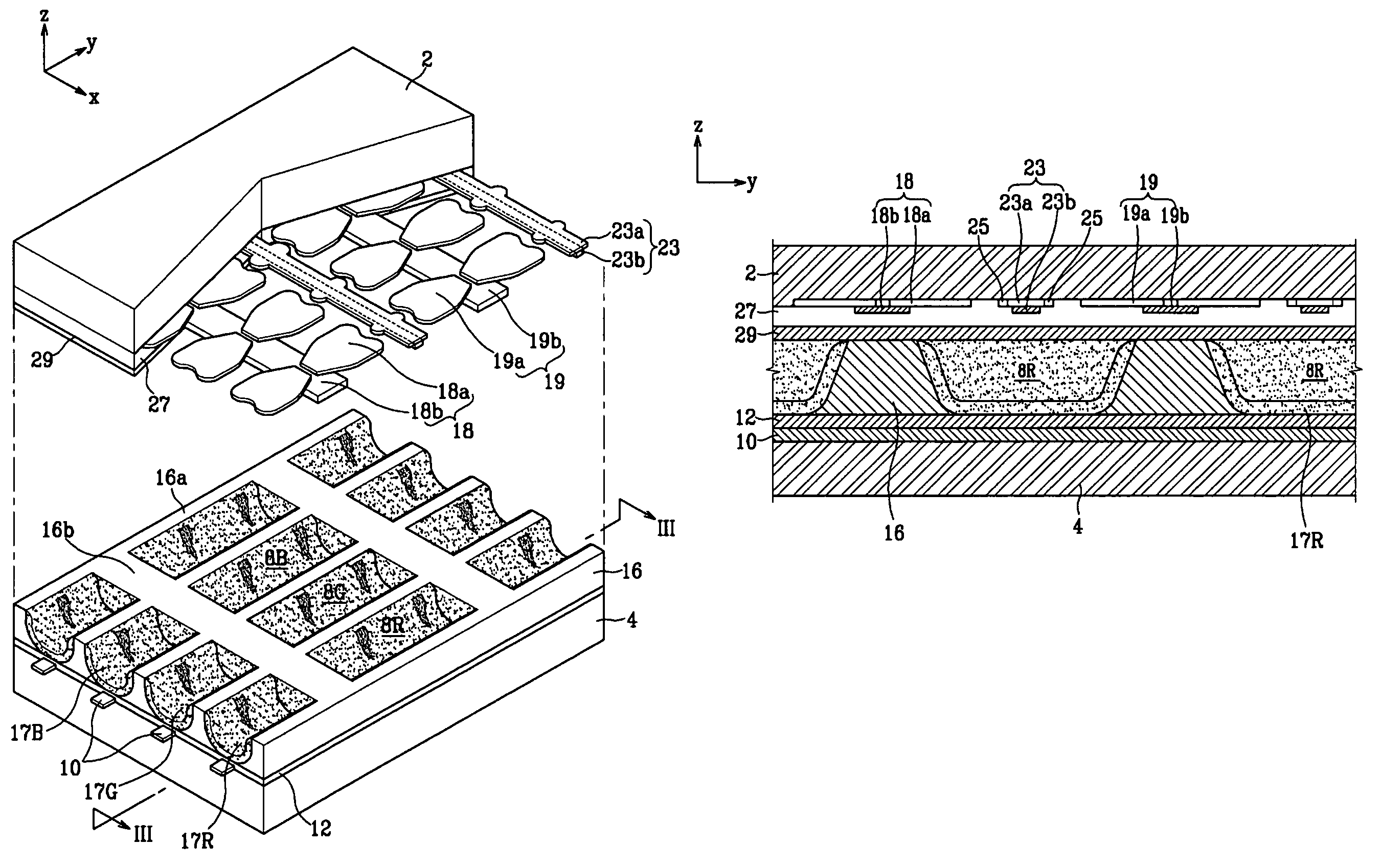
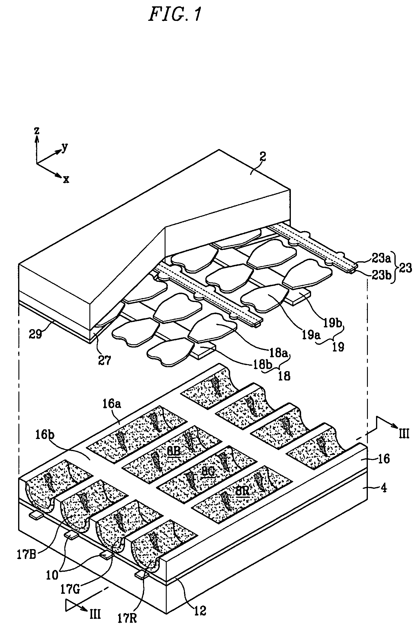
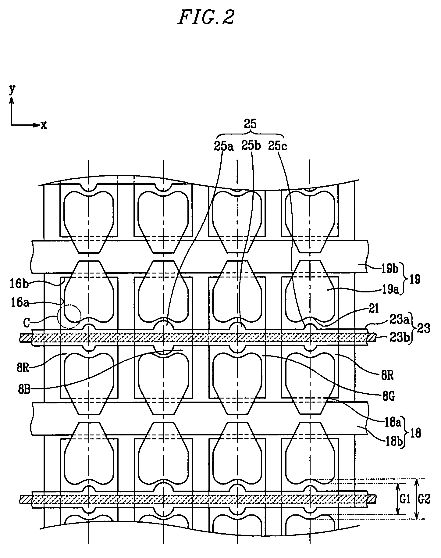
[0024]FIG. 1 is a partial exploded perspective view showing a PDP according to an exemplary embodiment of the present invention, and FIG. 2 and FIG. 3 are a partial plan view showing the PDP of FIG. 1 and a sectional view taken along line III-III of FIG. 1, respectively.

[0025]Referring to FIG. 1, FIG. 2 and FIG. 3, the PDP may include a first substrate 2 and a second substrate 4 facing one another with a gap therebetween, and a plurality of discharge cells 8R, 8G, 8B defined by barrier ribs 16 in the gap.

[0026]Address electrodes 10 may be formed on an inner surface of the second substrate 4 along a first direction (i.e., along direction y in the drawings), and a first dielectric layer 12 may cover the address electrodes 10. The address electrodes 10 may be arranged such that they substantially correspond to centers of widths of the discharge cells 8R, 8G, 8B, where the widths are along direction x.

[0027]The barrier ribs 16 may be formed on the first dielectric layer 12 to define the...


PUM


Abstract

A plasma display panel including first and second substrates facing one another with a gap therebetween, address electrodes formed on the first substrate along a first direction, barrier ribs mounted in the gap and defining a plurality of discharge cells, first and second electrodes formed on the second substrate along a second direction, which is substantially perpendicular to the first direction, and third electrodes extending along the second direction between pairs of the first and second electrodes. Areas of the third electrodes vary according to the color of the discharge cell over which the third electrodes are formed.

Description

CROSS REFERENCE TO RELATED APPLICATION[0001]This application claims priority to and the benefit of Korean Patent Application No. 10-2004-0016811, filed on Mar. 12, 2004, which is hereby incorporated by reference for all purposes as if fully set forth herein.BACKGROUND OF THE INVENTION[0002]1. Field of the Invention[0003]The present invention relates to a plasma display panel (PDP), and more particularly, to a PDP that minimizes differences in discharge voltages of discharge cells.[0004]2. Description of the Background[0005]Generally, a PDP is a next-generation flat panel display that utilizes gas discharge to display images. Anywhere from a few hundred thousand to a few million discharge cells may be formed in a matrix configuration within the PDP. Depending on discharge cell structure and driving voltage waveforms, the PDP may be classified as a direct current (DC) PDP or an alternating current (AC) PDP.[0006]In a conventional surface discharge AC PDP, address electrodes, barrier r...

Claims


Application Information

Patent Timeline
Patent Type & Authority Patents(United States)
IPC IPC(8): H01J17/49G09G3/10G09G3/28
CPCH01J11/12H01J11/26H01J11/28F24F6/10F24F6/18F24F2006/008
Inventor YI, JEONG-DOO
Owner SAMSUNG SDI CO LTD
Why Eureka
Try Eureka