System and method for optical coherence imaging

a coherence imaging and optical coherence technology, applied in the field of imaging probes and systems for biological samples, can solve the problems of significant aberration, large effect, and difficult longitudinal pullback, and achieve the effect of reducing astigmatism and reducing astigmatism

Active Publication Date: 2008-04-29
THE GENERAL HOSPITAL CORP
View PDF235 Cites 460 Cited by
  • Summary
  • Abstract
  • Description
  • Claims
  • Application Information

AI Technical Summary

Problems solved by technology

Due to the cylindrical shape of the sheath, however, its lens characteristics may be undesirable and, in particular, can introduce significant aberrations.
One of the most significant aberrations of the sheath is astigmatism, an effect that increases dramatically when using narrow diameter sheaths.
Although a rotation of the internal components within a water-filled sheath is possible, a longitudinal pull-back is problematic due to the viscosity of the fluid and turbulence.
As a result, such probes are difficult to manufacture.
Additionally, these designs lack mechanical integrity and require an additional structure, such as an outer protective sleeve, to avoid mechanical failure.
This requirement may result in a larger probe diameter and longer rigid length than otherwise might be possible.
Additionally, a beam deflector such as a prism cannot be directly bonded to the spherical surface of the ball lens, thus requiring an additional housing for its positioning and mechanical fixture.

Method used


Image

  • System and method for optical coherence imaging
  • System and method for optical coherence imaging
  • System and method for optical coherence imaging

Examples


Embodiment Construction

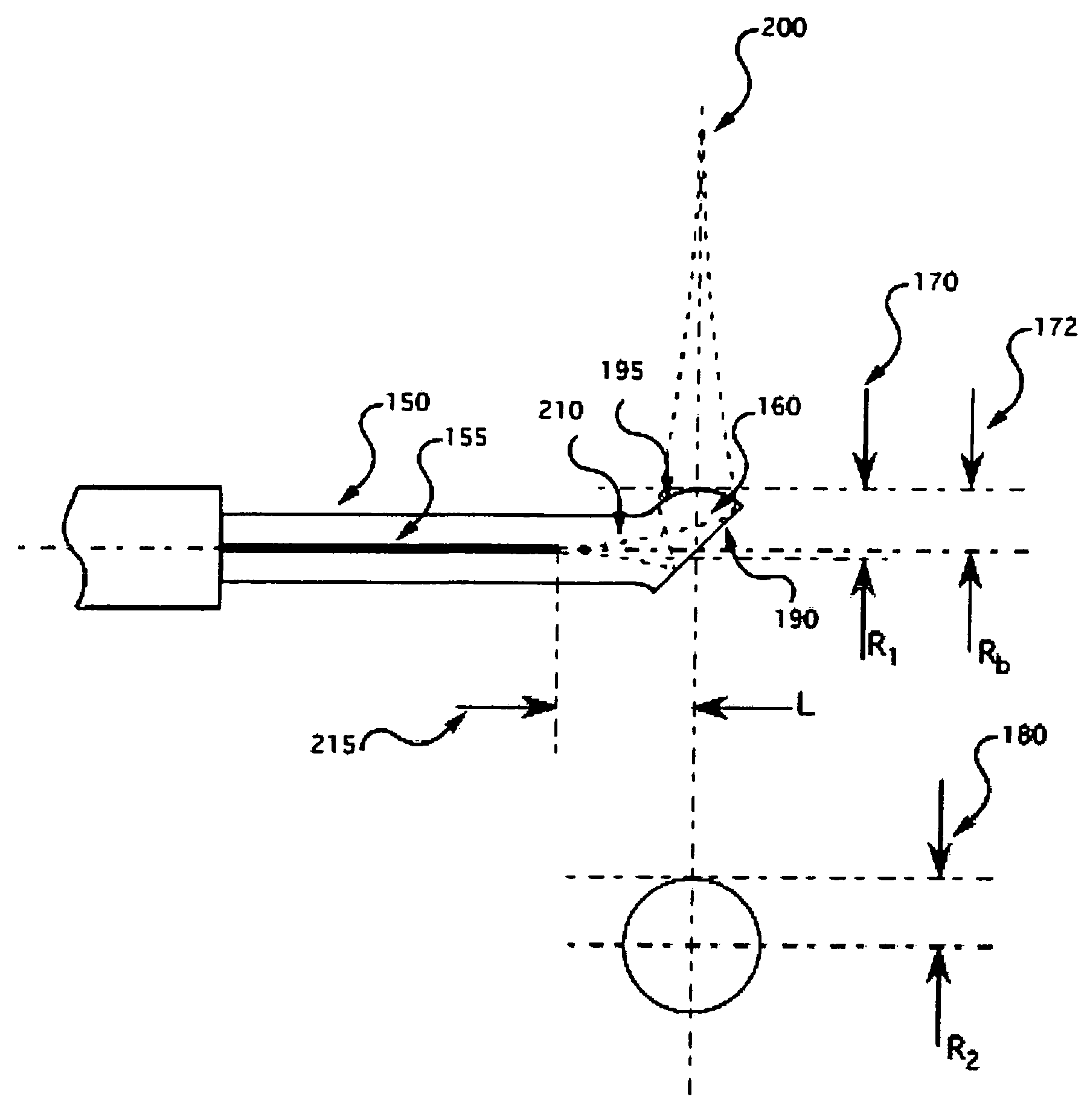
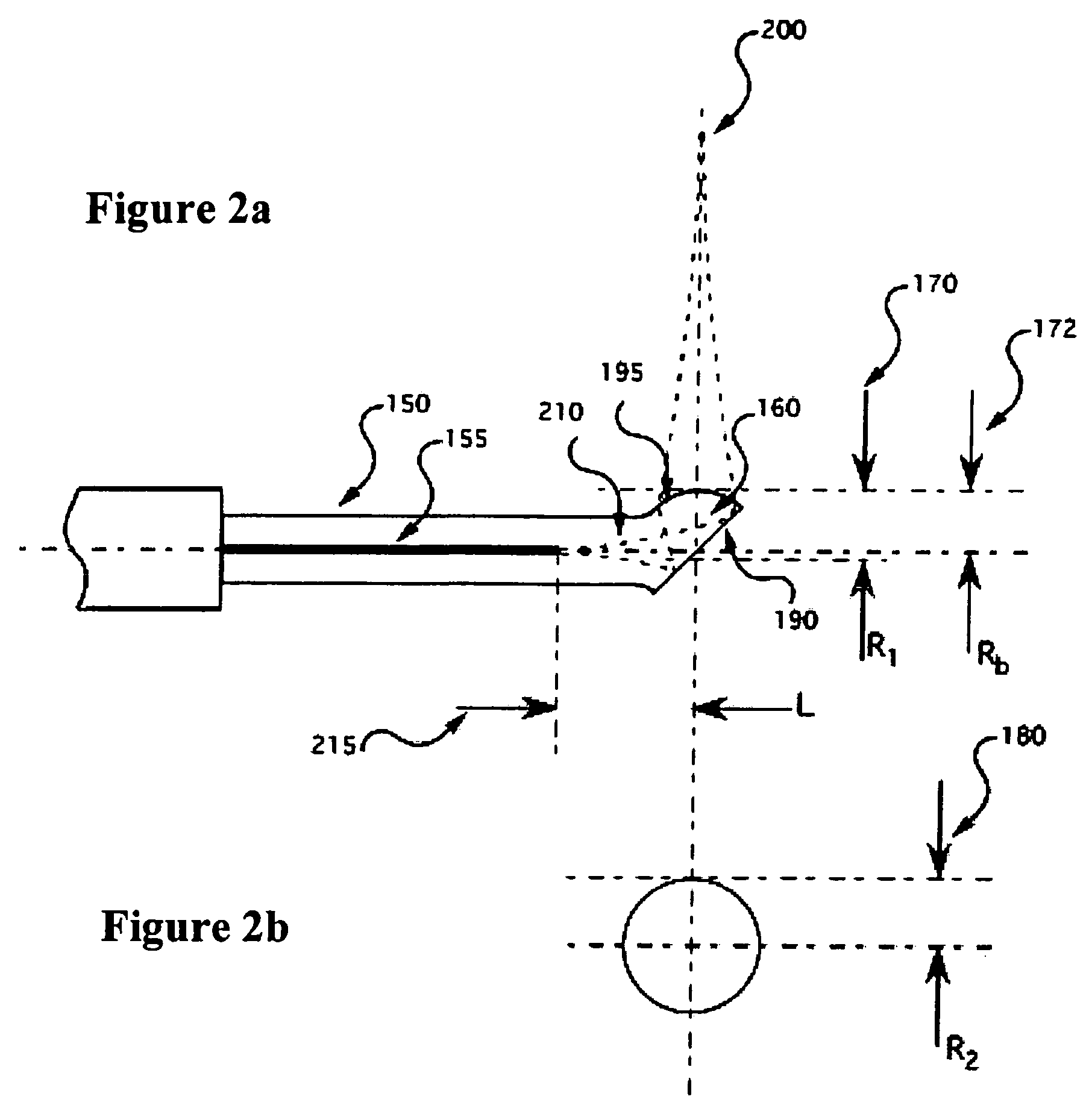
[0040]FIG. 2 depicts an exemplary embodiment of a sculptured tip optical fiber probe according to the present invention. Features of this exemplary embodiment of the probe can include a optical fiber 150 (e.g., preferably a single-mode fiber), in which a distal end of the optical fiber can include a portion of a prolate spheroidal ball 160, monolithic with the fiber. A prolate spheroid may be characterized by a sphere that has been pulled or extended along an axis separating its poles. Over a predetermined (e.g., small) portion 195 of the surface of the ball 160, the surface can be characterized as having two distinct radii of curvature, R1 170 and R2 180 (as shown in a side view of FIG. 2a, and an end view of FIG. 2b) of the fiber distal end. The radius of curvature R1 170 is greater than the physical radius Rb 172 of the ball. The radius of curvature R2 180 is approximately equivalent to the physical radius 172.

[0041]The distal end of the fiber can be further characterized by an a...


PUM


Abstract

Apparatus and method are provided for transmitting at least one electro-magnetic radiation is provided. In particular, at least one optical fiber having at least one end extending along a first axis may be provided. Further, a light transmissive optical arrangement may be provided in optical cooperation with the optical fiber. The optical arrangement may have a first surface having a portion that is perpendicular to a second axis, and a second surface which includes a curved portion. The first axis can be provided at a particular angle that is more than 0° and less than 90° with respect to the second axis.

Description

CROSS-REFERENCE TO RELATED APPLICATION(S)[0001]The present invention claims priority from U.S. patent application Ser. No. 60 / 614,228 filed on Sep. 29, 2004, the entire disclosure of which incorporated herein by reference.STATEMENT REGARDING FEDERALLY SPONSORED RESEARCH[0002]The invention was made with the U.S. Government support under Grant Number DAMD17-99-2-9001 awarded by the U.S. Department of the Army. Thus, the U.S. Government has certain rights in the invention.FIELD OF THE INVENTION[0003]The present invention relates generally to imaging probes and systems for imaging biological samples, and more particularly, to optical fiber probes and optical imaging systems which are capable of using such probes for imaging of the biological samples.BACKGROUND INFORMATION[0004]In vivo optical imaging of internal organs of a patient is commonly performed through a fiber-optic catheter. Many clinical areas such as cardiology, interventional radiology and gastroenterology require a small d...

Claims


Application Information

Patent Timeline
Patent Type & Authority Patents(United States)
IPC IPC(8): G02B6/32G02B6/02G02B6/028G02B6/032G02B6/036G02B6/44G02B6/42G02B6/12G02B6/26
CPCA61B5/0066A61B5/0084G02B6/2552G02B6/262A61B5/6852G02B6/2856G01N21/47A61B5/00G02B23/24H04J14/0267
Inventor SHISHKOV, MILENBOUMA, BRETT EUGENETEARNEY, GUILLERMO J.
Owner THE GENERAL HOSPITAL CORP
Why Eureka
Try Eureka