

Instrument panel structure for vehicles
a technology for instruments and dashboards, applied in vehicle components, pedestrian/occupant safety arrangements, dashboards, etc., can solve problems such as unsatisfactory shock absorption for drivers/passengers
- Summary
- Abstract
- Description
- Claims
- Application Information
AI Technical Summary
Benefits of technology
Problems solved by technology
Method used
Image

Examples
first embodiment
of the Invention
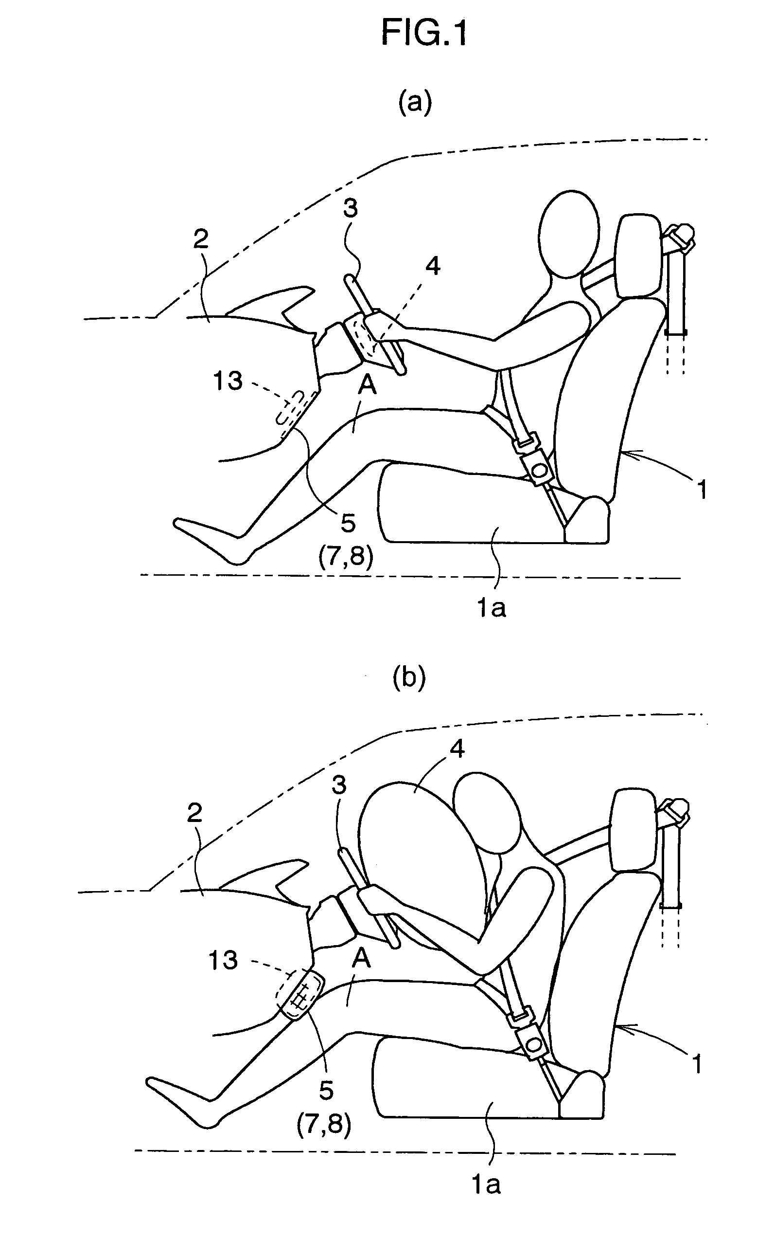
[0065]In this embodiment, as illustrated in FIG. 1(a), an instrument panel 2 and a steering wheel 3 are arranged forwardly of a driver's seat 1, and an air bag 4 is mounted inside the steering wheel 3. The instrument panel 2 made of synthetic resin has a lower panel portion 5 made of synthetic resin and disposed below the steering wheel 3.
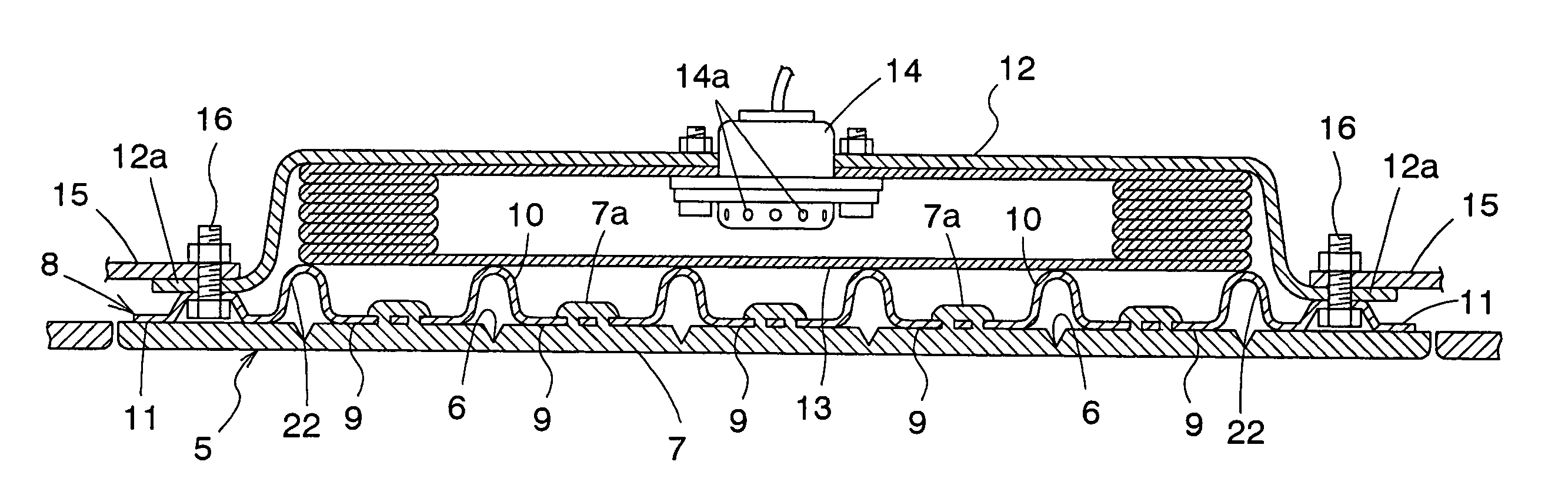
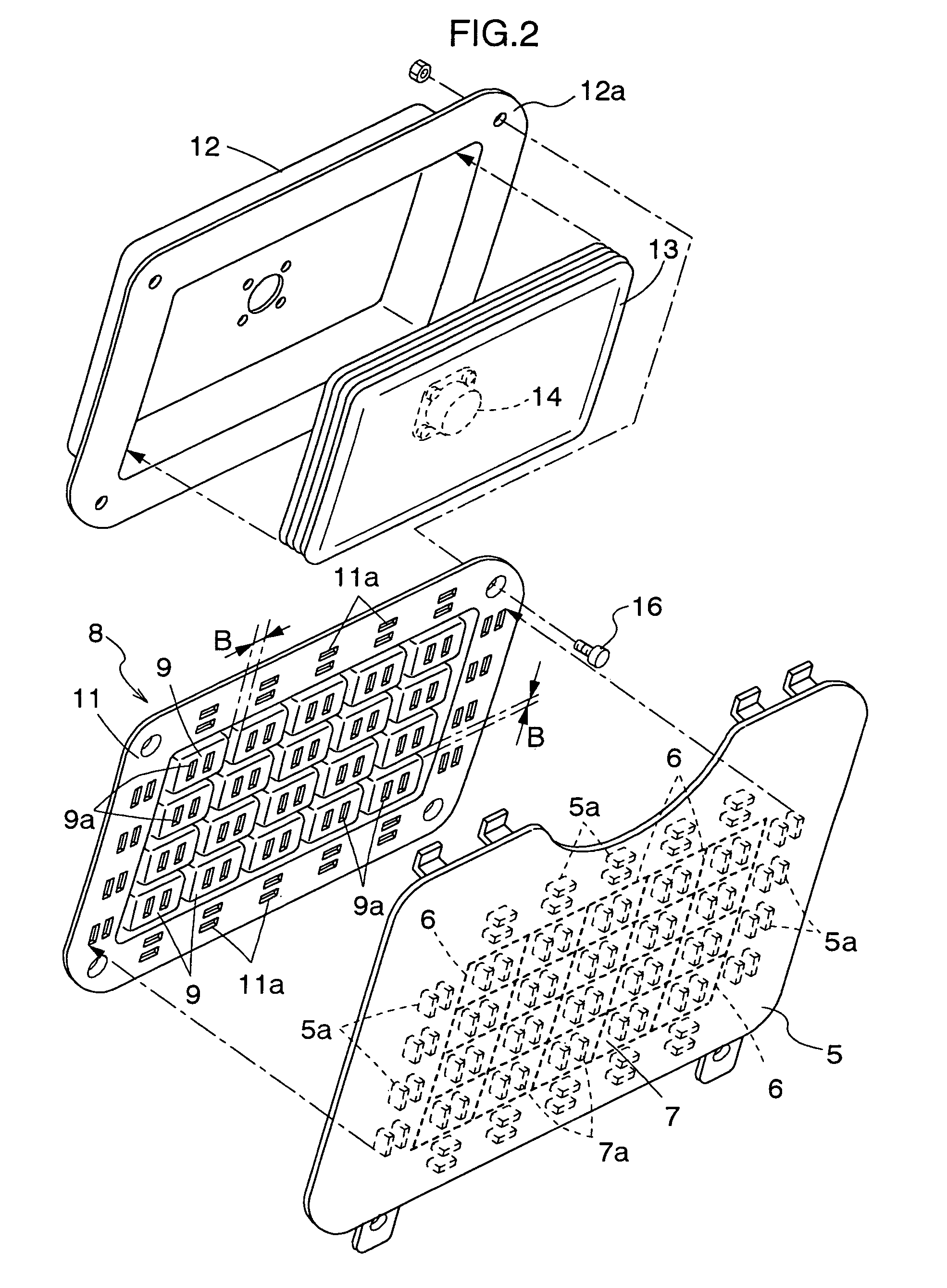
[0066]As shown in FIGS. 2 and 3, a plurality of grooves 6 are formed on the back surface of the lower panel portion 5 which run longitudinally and transversely in a grid shape. A rectangular receiving portion 7 surrounded by the outermost grooves 6 is defined on the lower panel portion 5. Numerous projections 5a and 7a are integrally formed on the back surface of the lower panel portion 5 at outer peripheries thereof and the back surface of the receiving portion 7, respectively.
[0067]As illustrated in FIGS. 2 and 3, an absorbing member 8 is formed by press-working a plate material made of metal or reinforced synthetic resin (multipl...
second embodiment
of the Invention
[0075]In the foregoing embodiment of the invention, as shown in FIG. 5, a pad member 17 such as of a urethane material may be disposed between the absorbing member 8 and the lower air bag 13. In this case, the pad member 17, preferably, has a flat plate-like shape with a predetermined thickness.
[0076]According to such a construction, as illustrated in FIGS. 5 and 6, when the lower air bag 13 is inflated to push the absorbing member 8 toward the seat 1 positioned rearward, thereby to extend the bend portions 10 and the connecting portions 22 of the absorbing member 8 by plastic deformation to separate the face portions 9 of the absorbing member 8 from each other and rapidly move toward the seat 1 positioned rearward, the entire absorbing member 8 is maintained in a general planar shape by to the pad member 17.
third embodiment
of the Invention
[0077]The present invention may be constructed as shown in FIGS. 7 and 8 instead of the above-described first embodiment or the second embodiment.
[0078]In the first and second embodiments set forth above, as illustrated in FIGS. 3 and 5, the flange portion 12a of the supporting member 12 and the flange portion 11 of the absorbing member 8 are connected through the bolts 16 to the brackets 15 disposed inside the instrument panel 2. On the other hand, in FIG. 7, only the flange portion 12a of the supporting member 12 is connected to the brackets 15 through the bolts 16.
[0079]The flange portion 11 and connecting portions 22 of the absorbing member 8 (see FIGS. 2 and 3) are eliminated, and wires 18 are provided to connect the brackets 15 and the absorbing member 8. In this case, these wires 18 are slightly loose. With respect to the grooves 6, the outermost grooves 6a are formed deeper than the inner grooves 6b to be easily breakable. The other parts have the same constr...
PUM
 Abstract
Description
Claims
Application Information