Oxygen bottle carrier appliance

a technology for carrying oxygen bottles and oxygen bottles, which is applied in the direction of supplementary fittings, walking aids, physical therapy, etc., can solve the problems of potentially damaging falls, unsatisfactory attempts to mount oxygen bottles on walkers, and impractical use of oxygen bottles

Inactive Publication Date: 2008-05-13
HAMILTON ROGER H +1
View PDF31 Cites 25 Cited by
  • Summary
  • Abstract
  • Description
  • Claims
  • Application Information

AI Technical Summary

Benefits of technology

[0006]It is a further primary object of the present invention to provide for the safety of patients who require the use of both oxygen and a walker or other appliance, such as a wheelchair, when moving from place to place.
[0007]It is a still further object of the present invention to mount an oxygen bottle upon a walker or other appliance in a stable condition that will n

Problems solved by technology

However, these devices require the use of one of the patient's hands to propel the bottle, thus rending them impractical for use when the patient must also use a walker to get about.
Attempts to mount an oxygen bottle upon a walker have been proven to be less than satisfactory because the bottle typically renders the walker unstable and extremely difficult to manage.
This, in turn, can pose a dangerous situation for an elderly or weak patient which can lead to a potentially damaging fall.
However, there are associated problems with such carriers.
That is to say, it is extremely difficult

Method used


Image

  • Oxygen bottle carrier appliance
  • Oxygen bottle carrier appliance
  • Oxygen bottle carrier appliance

Examples


first embodiment

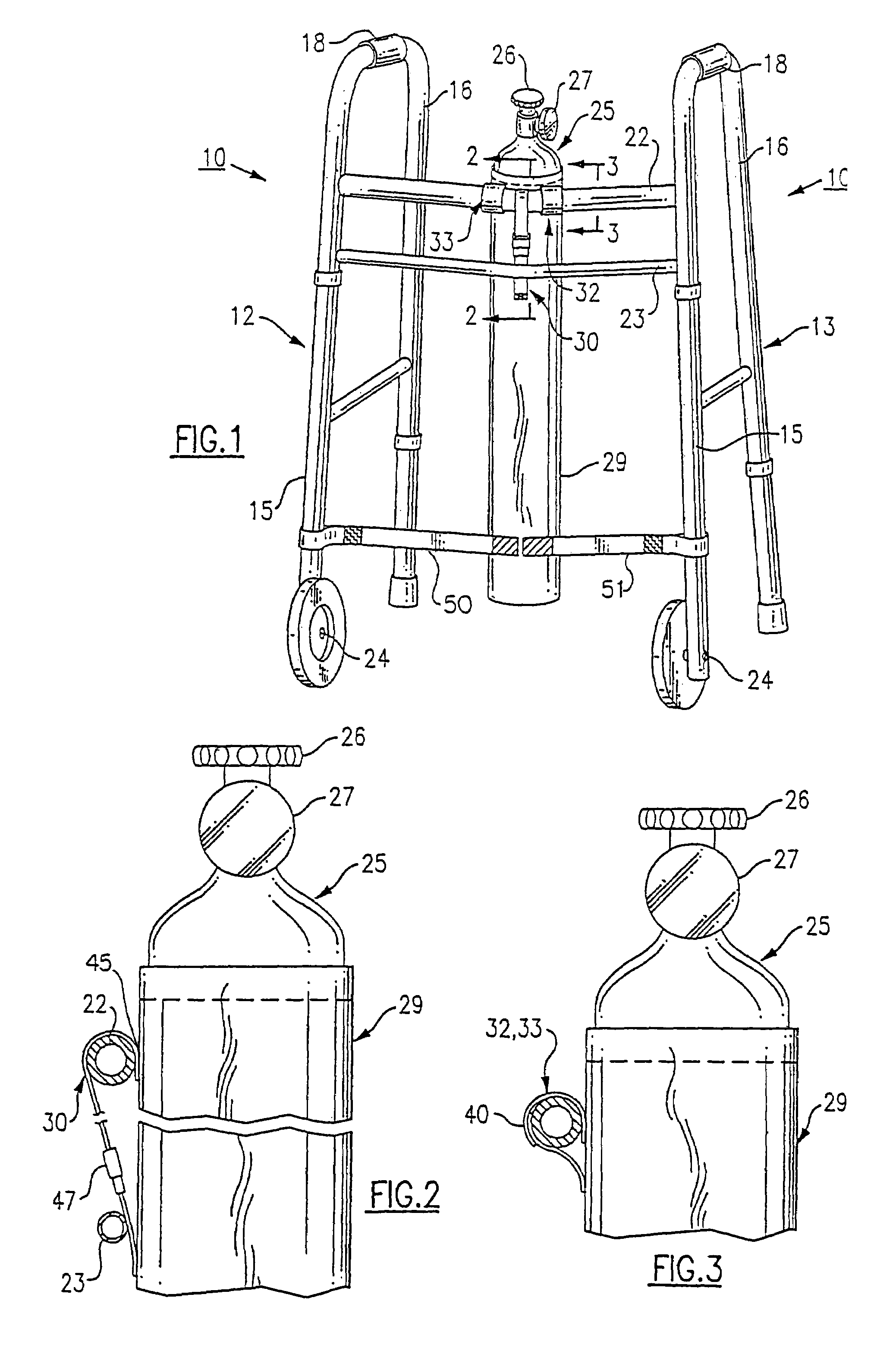
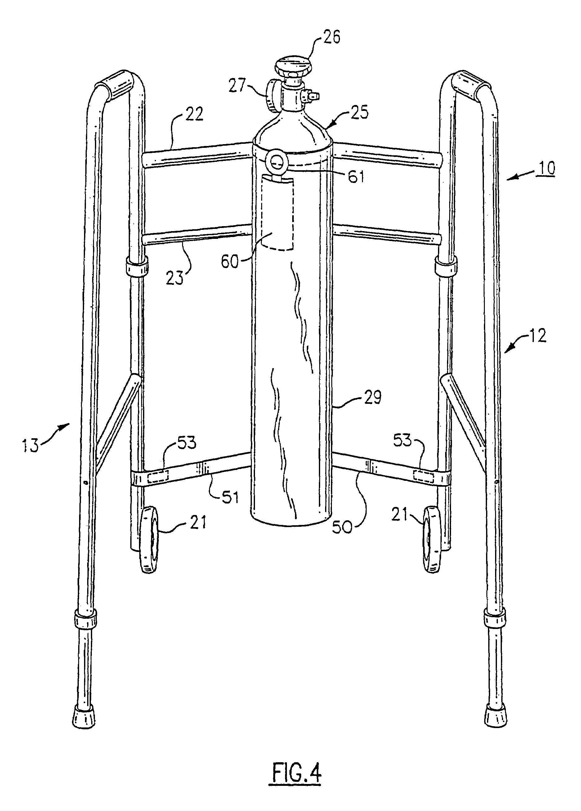
[0019]With regard to the first embodiment, and turning now to FIG. 1, there is illustrated a walker, generally referenced 10, that includes an oxygen bottle carrier made in accordance with the present invention. The walker 10 is of typical construction and includes a pair of side frames 12 and 13. Each side frame 12, 13 is of similar construction and includes a vertically disposed front leg 15 and a vertically disposed rear bar 16. A horizontally disposed handrail 18 is integrally joined to the front and rear legs 15, 16 and provides a means by which a patient can securely grip and control the walker 10 when situated between the two side frames 12, 13. A lower rail 20 also extends between the front and rear legs 15, 16 of each side frame 12, 13 in order to provide additional strength to the walker 10.

[0020]The two side frames 12, 13 are supported in a spaced apart relationship by an upper cross member 22 and a lower cross member 23 that are secured between the two front legs 15 of t...

second embodiment

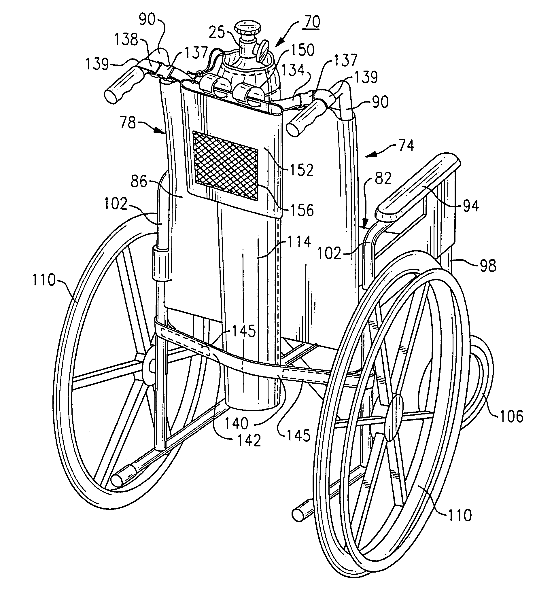
[0027]Referring now to FIGS. 5-7, there is described an oxygen bottle carrier 70 made in accordance with the present invention. The carrier in this instance is uses in conjunction with a wheelchair 74 shown most particularly in FIG. 5, the wheel chair including a frame 78 that is defined by a seat 82 and a backrest 86. The frame 78 further includes a pair of spaced vertical handles 90 disposed on either side of the backrest 86 used for pushing the wheelchair 74, whereas the seat 82 includes armrests 94 and respective vertically extending front and rear legs 98, 102. The wheelchair 74 further includes a pair of swivelable front wheels 106 connected to a lower portion of the front legs 98 of the frame 78 as well as a pair of rear wheels 110 attached to the lower portion of each of the rear legs 102. The above construction defines the majority of wheelchairs in general, whose construction in and of itself is acknowledged as well known in the field and not forming an essential part of t...


PUM


Abstract

A carrier for retaining an oxygen bottle said carrier comprising a flexible open-top container adapted for maintaining a close fitting relationship with an oxygen bottle, said container including an upper mouth portion made at least partially from a stiff material to enable an oxygen bottle to be loaded therein vertically; and a flexible upper bottle retaining portion, for preventing said bottle from falling out of said carrier.

Description

CROSS REFERENCE TO RELATED APPLICATION[0001]This application is a continuation in part application of U.S. patent application Ser. No. 10 / 037,207, filed Jan. 4, 2002, now U.S. Pat. No. 6,672,321, the entire contents of which are herein incorporated by reference.FIELD OF THE INVENTION[0002]This invention relates generally to the field of oxygen bottle carrying apparatus, particularly for individuals who have difficulty breathing and, in particular, to an oxygen bottle carrier that can be attached for use to an orthopedic appliance, such as a walker or a wheelchair.BACKGROUND OF THE INVENTION[0003]Many patients and, in particular, elderly patients, have breathing disorders that necessitate the use of oxygen. In certain extreme cases, the patient must have oxygen for breathing available at all times and, in particular, when the patient is exerting him or herself, as for example, when walking. Oxygen bottle caddies on wheels are presently available for transporting oxygen bottles. Howev...

Claims


Application Information

Patent Timeline
IPC IPC(8): A61H3/04B60R9/06
CPCA61H3/04A61H2003/046A61H2201/107
Inventor HAMILTON, ROGER H.JORDAN, PETER G.
Owner HAMILTON ROGER H
Why Eureka
Try Eureka