Turbocharger shaft bearing system

a technology of bearing system and turbocharger shaft, which is applied in the direction of bearing unit rigid support, positive displacement liquid engine, piston pump, etc., can solve the problems of substantial friction loss of collar-style rotating thrust bearings

Inactive Publication Date: 2008-05-13
CPI HLDG
View PDF8 Cites 48 Cited by
  • Summary
  • Abstract
  • Description
  • Claims
  • Application Information

AI Technical Summary

Benefits of technology

[0009]In addition, the split bearing carrier may further define an oil flow chamber disposed axially between the bearing units, with the inboard-end segments of the bearing sleeves defining at least one oil inflow port for receiving a flow of lubricant into said oil flow chamber. This oil flow beneficially lubricates the bearing units at the split interface between the bearing sleeves, and further provides an axial thrust load local to the split interface from the hydraulic pressure being fed into the turbocharger. Such hydraulic pressure effectively applies an axial thrust load upon the two bearing units, thereby supplementing the mechanical thrust pre-load provided by the spring member.

Problems solved by technology

However, such collar-style rotating thrust bearings have been associated with substantial friction losses.

Method used


Image

  • Turbocharger shaft bearing system
  • Turbocharger shaft bearing system
  • Turbocharger shaft bearing system

Examples


Embodiment Construction

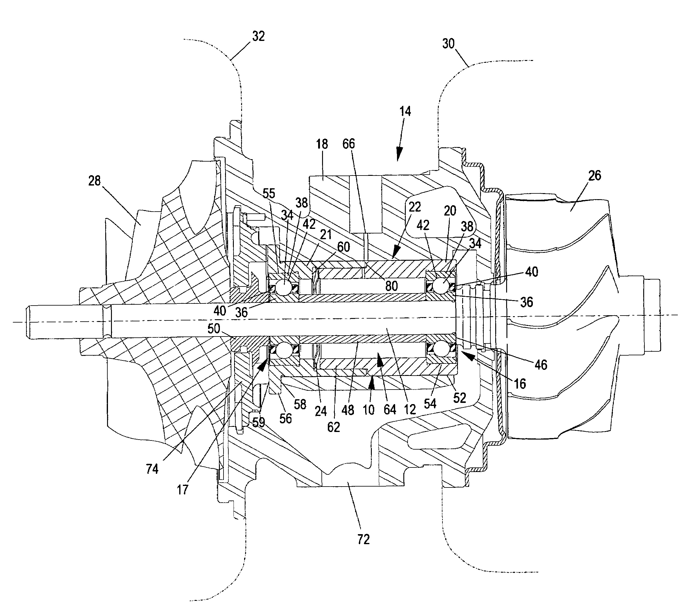
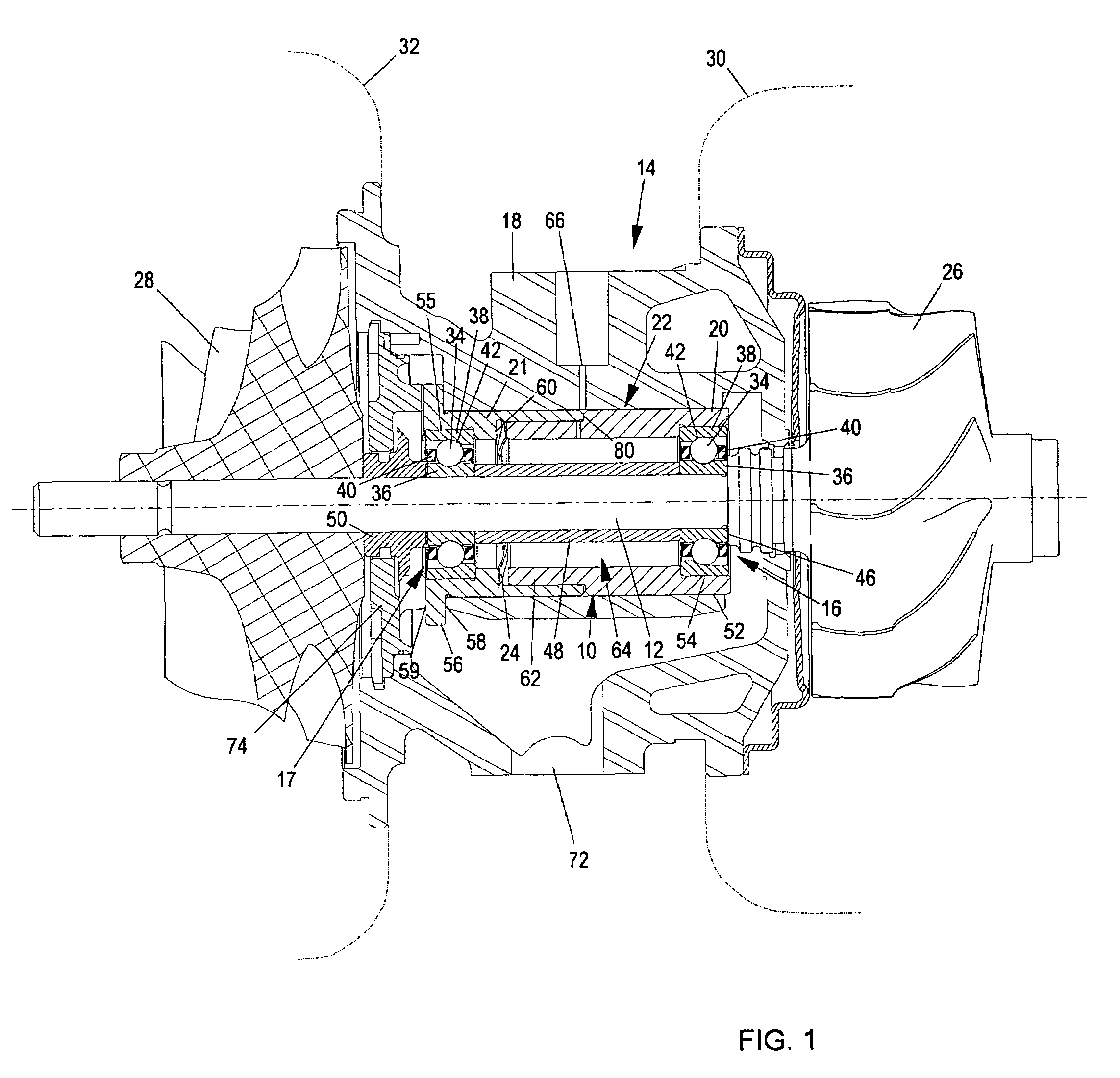
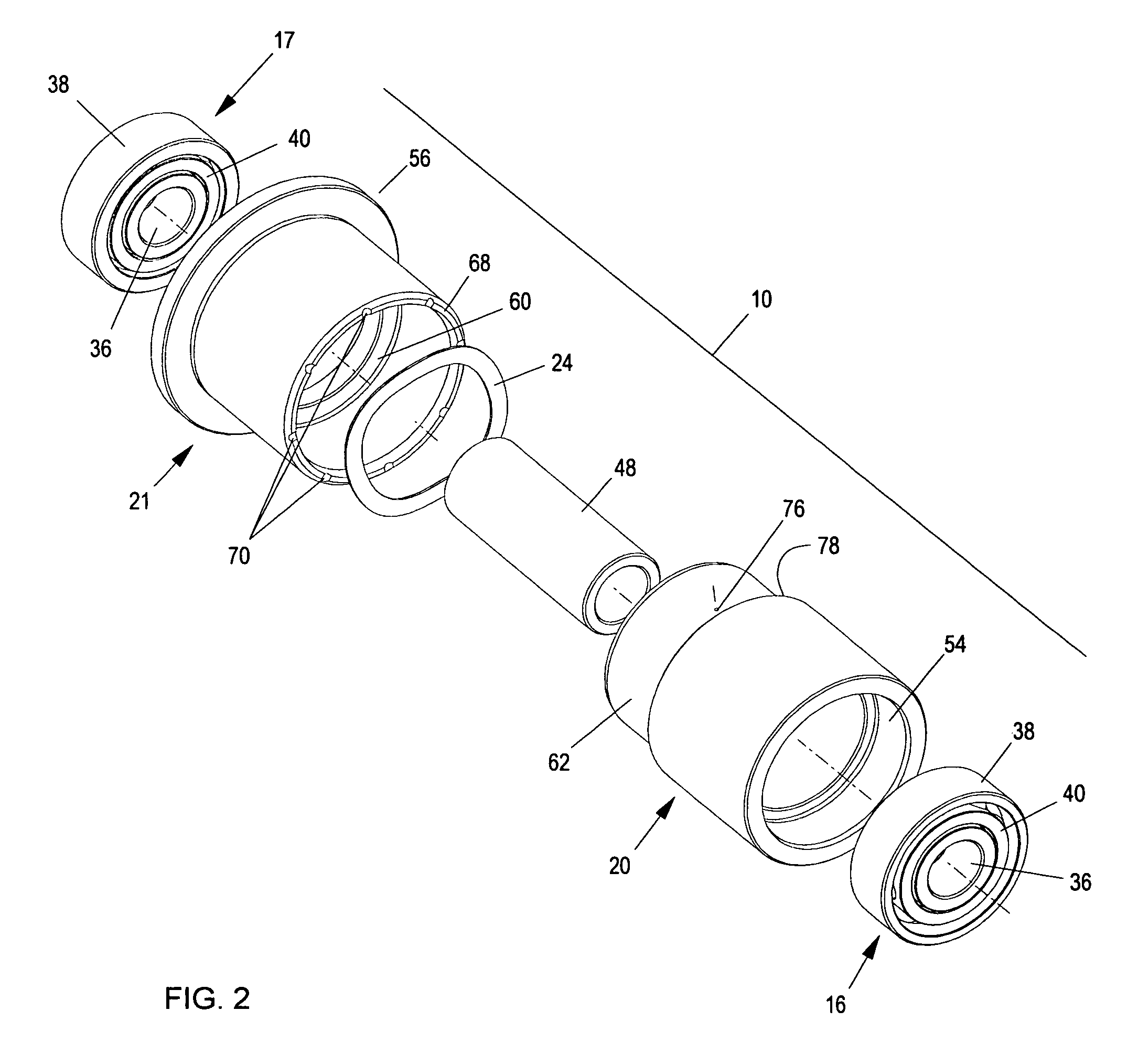
[0015]As shown in the exemplary drawings, an improved turbomachine shaft bearing system referred to generally in FIGS. 1 and 2 by the reference numeral 10 is provided for rotatably supporting a rotating shaft 12 in high speed machinery such as the illustrative turbocharger 14 (FIG. 1). The shaft bearing system 10 includes a pair of axially spaced angular contact ball bearings or ball bearing units 16 and 17 for rotatably supporting the shaft 12 within a housing such as the illustrative turbocharger center housing 18. In accordance with the invention, the bearing units 16, 17 are carried respectively within a pair of bearing sleeves 20 and 21 defining an axially split bearing carrier 22. Thrust pre-load means such as a mechanical spring member 24 applies a thrust pre-load of predetermined axial and substantially constant axial force to both of the bearing sleeves 20, 21, which in turn transmit the thrust pre-load force to the associated angular contact bearing units 16, 17.

[0016]The ...


PUM


Abstract

An improved bearing system is provided for use in high speed rotating machinery such as a turbocharger, wherein a turbocharger shaft is rotatably supported at opposite ends by a pair of angular contact bearings subjected to a predetermined and substantially constant thrust pre-load. The angular contact bearings are carried respectively within a pair of generally cylindrical bearing sleeves which cooperatively define an axially split bearing carrier mounted within a turbocharger housing. A spring reacts between these bearing sleeves for applying a substantially constant axial thrust pre-load transmitted by the bearing sleeves to the angular contact bearings. The mechanical spring thrust pre-load may be supplemented by an hydraulic axial thrust load attributable to oil circulated through the split bearing carrier.

Description

BACKGROUND OF THE INVENTION[0001]This invention relates generally to improvements in bearing systems for use in high speed rotating machinery or turbomachines, particularly such as a turbocharger for supplying charge air at elevated pressure to an internal combustion engine. More particularly, this invention relates to an improved turbomachine bearing system of the type having a high speed rotary shaft supported by a pair of angular contact bearings, wherein the angular contact bearings are subjected to a substantially constant axial thrust pre-load.[0002]Turbochargers are well known in the art for use in supplying charge air under pressure to an internal combustion engine for the purpose of increasing engine performance. Such turbochargers generally comprise a turbine wheel and a compressor wheel or impeller mounted on a common shaft which is supported by suitable bearings for high speed rotational operation. The turbine wheel is positioned within a turbine housing shaped for flow-...

Claims


Application Information

Patent Timeline
Patent Type & Authority Patents(United States)
IPC IPC(8): F16C25/06F04B17/00
CPCF01D25/16F16C19/54F16C25/08F16C35/077F05D2220/40F05D2240/50F05D2250/611F16C2360/24F16C19/548F16C25/083
Inventor MCKEIRNAN, JR., ROBERT D.
Owner CPI HLDG
Why Eureka
Try Eureka